
Ice Navigation in Canadian Waters
Chapter 5: Vessel design and construction for ice operations
Table of Contents
- Preface
- Chapter 1: Icebreaking and Shipping Support Services
- Chapter 2: Regulations and Guidelines
- Chapter 3: Ice Climatology and Environmental Conditions
- Chapter 4: Navigation In Ice Covered Waters
- Chapter 5: Vessel Design and Construction for Ice Operations
- Annex I: Terminology for Ice, Navigation and Vessel Design
- Annex II: Reference Material
Chapter 5: Vessel design and construction for ice operations
5.1 Hull form design
5.1.1 Bow shape
The bow shape of a Type vessel is typical of vessels designed for operation in open water, typically with a bulbous bow, which is particularly vulnerable to thick first year and old ice floes. As such, it is designed only to force ice, that is, to push ice away from the ship. Therefore, operators of Type vessels should not attempt to break ice by aggressive action. The bow shapes for icebreakers may be described by the stem, flare, buttock, and water-line angles. These angles contribute to the icebreaking, submergence, and clearing efficiency. Recent trends in the design of icebreakers are to increase flare angles, to reduce water-line angles, and to reduce stem and buttock angles.
Some icebreaker bow shapes can be referred to as conventional or traditional in that they represent a progressive improvement in icebreaking resistance while retaining the smooth hull which offers least resistance in open water (figure 76). Other bows can be referred to as unconventional or non-traditional, in that they are a distinct departure from smooth hull shapes (figure 77). It would appear from past experience that the best traditional shapes have performed almost as well in level ice as the best non-traditional shapes.
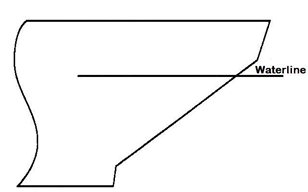
Figure 76 - Conventional icebreaker bow shape
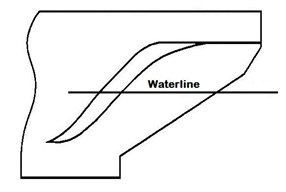
Figure 77 - Unconventional bow shape
5.1.2 Midbody shape
The selection of a midbody shape must consider its effect on resistance, manoeuvrability, construction cost, and the required deadweight. The midbody may be characterized by flare angle (over the full depth or locally), parallel midbody, and longitudinal taper.
5.1.3 Stern shape
The stern design on icebreaking vessels is controlled mainly by the number of propellers, which is a function of the required power and operational requirements. The stern must, to the greatest extent possible, provide protection to the rudder(s) and propeller(s). To provide this protection, a number of design options can be selected. The conventional stern, typical of CCG icebreakers, is rounded to provide good icebreaking astern performance, and is usually fitted with an ice horn to protect the rudder. A transom, or ramped, stern is installed on several icebreakers. The objective of this stern is to allow the broken ice pieces to move upward to the surface well ahead of the propeller(s).
There are several design features that can be added to sterns to protect the rudder(s) and propeller(s):
- an ice horn fitted to the hull immediately above and aft of the rudder provides protection to the rudder during backing operations
- rudder stops can be fitted to protect the rudder and steering gear from damage during backing operations when ice could force the rudder away from the mid vessels position
- propeller nozzles provide some protection to the propeller(s)
- deflecting fins are sometimes added to the hull in an effort to deflect ice pieces away from the propeller(s)
- the ice-clearing island (or ice skirt) is a wedge protruding below the ship's hull from the baseline forward of the propellers, and slopes up to the water-line aft of the propeller. The objective is to guide ice pieces away from the propeller(s)
5.2 Structural design
5.2.1 Loading
The design of structure for icebreakers and other ice-capable vessels requires a knowledge of the magnitude of ice loads, which are influenced by: hull shape, displacement, power, speed, ice confinement, and ice type.
The ice load experienced by a ship's hull will vary between hull areas. The bow area experiences the highest loads, while the bottom will generally experience the lowest loads. Figure 78 illustrates the hull areas for a Type ship. Research has shown that the ice load is not evenly distributed over the area of contact between the hull and the ice. The contact area shape is thought to be elliptical, with the major axis about eight times longer than the minor axis. For bow impacts, this elliptical shape is assumed to be symmetrical about either side of the stem.
In the International Association of Classification Societies concerning Unified Requirements for Polar Class Vessels, the vessel’s hull are divided into areas reflecting the magnitude of the loads that are expected to act upon them. In the longitudinal direction, there are four regions: Bow (forward region), Bow Intermediate (a transition between the forward and mid vessel regions), Midbody (mid vessel region) and Stern (aft region).
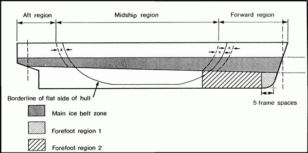
Figure 78 - Hull areas for a Type ship
Text version: Hull areas for a Type ship
An example of a simplified ship architecture diagram that mentions main sections of a vessel's construction: aft, mid and forward. An overview of the ice belt zone near the waterline in relation to the forefoot region (keel to bow) where the hull is usually reinforced depending on a vessel's ice class.
5.2.2 Structural arrangement
The vessel's structure must be designed, and arranged, to withstand the loads imposed globally and locally. The most common global consideration is an adequate hull girder section modulus for the highest ice class vessels in a “beaching condition”. This condition can occur when the vessel is ramming an ice floe and the bow rises out of the water to rest on the floe. Lower Arctic Class vessels, Type vessels, and vessels which are not intended solely for Arctic operations, such as those which operate in the Great Lakes or other inland waters, do not necessarily require higher section modulus than open water vessels, because bending stresses incurred during normal operations for vessels do not exceed those experienced in heavy seas. The local structure must resist failure caused by bending, shearing, buckling, and tripping. Although bending failure has traditionally been considered the most likely failure mode, experience gained from Arctic operations indicates that frame buckling and tripping are more critical failure modes. A Type vessel should never be used so aggressively in ice that the bow rises up like an icebreaker, to break the ice by the weight of the vessel, however, a Type vessel in ballast which is trimmed too far by the stern may find floes becoming wedged under the bow for a considerable distance back from the stem. Bottom damage can easily occur if heavy ice-floes are forced against the bottom plating, which is normally lighter than the plating of the ice-belt.
In a traditional icebreaker structure, the shell plating is supported by main frames spaced about 40 centimetres apart. The main frames are supported by longitudinal stringers, and the stringers are supported by web frames or bulkheads. The grillage of major structure supports the global loads and the main frames support the local loads. This arrangement is based on the assumption that initial failure will occur from the bending collapse of the main frames, and, as a result, the span of these frames need to be short, hence the position of stringers. Failure with this type of structure is usually frame buckling and tripping.
Simpler structural arrangements have evolved from the recognition that frame buckling and tripping were the critical failure modes. Typical of such arrangements, the steel plating between two decks is supported by large main frames spaced further apart than those in the traditional arrangement, and is based on the assumption that the shell plating membrane strength can also be included in the strength calculations. The frames are designed against bending, buckling, and tripping, which results in heavier frames and eliminates the need for stringers. The resultant structural arrangement has thinner plates and larger main frames but very few components and connections, which is easier to construct and has lower construction costs.
5.2.3 Construction materials and behaviour at low temperatures
Structural integrity requires the proper selection of hull materials. The 2 primary groups of steel used in vessel construction are normal strength and high strength steels (referring to their minimum yield strength). Within each of these groups, there are several grades of steel which are assigned according to their chemical composition and other mechanical properties.
Based on past experience, the critical factor associated with the properties of steel in Arctic vessels is their resistance to brittle fracture from low temperatures and high loading conditions, typical of operations in ice. Low temperature is the most important environmental factor for the selection of materials when designing against brittle fracture. At low temperatures, the ductility and fracture toughness decreases; the steel becomes brittle, increasing the likelihood of a catastrophic brittle fracture. Such fracturing is more frequent above the water-line where steel is exposed to very low air temperatures.
The mariners on board a vessel in ice must be aware of the type of steel used in the construction of their ship. The shell expansion plan will be on board and it will show clearly the steel qualities used. If a vessel has no low temperature steel, it is important to avoid impacts with hard ice when the air temperatures are very low, or the vessel has been exposed to very low temperatures for a long period prior to navigating in ice.
5.3 Propulsion systems
Propulsion systems for ice-going vessels must be reliable, flexible with a view to redundancy, maintainable, and have high power-to-weight and power-to-space ratios. The 2 dominant propulsion systems in ice-going vessels are diesel-electric transmission with fixed-pitch propellers (typically installed on icebreakers), and diesel-mechanical transmission with controllable-pitch propellers. Vessels not required to break ice would normally have a diesel-mechanical transmission, with or without controllable-pitch propellers. The most recent development for icebreaker propulsion systems includes submerged azimuthing pod propulsion motors, which are proving to be very effective for both icebreakers and icebreaking cargo vessels. By eliminating the need for a rudder, these systems make vessels more manoeuvrable at the same time as they remove the threat of rudder damage.
5.3.1 Prime movers
The choice of prime mover is a function of task to be performed, area of operation, and economics. Diesel engines, steam turbines, and gas turbines are options currently used in either icebreakers or ice-going vessels.
Medium-speed diesel engines usually are unidirectional and require a separate system for astern operation which can be provided by a controllable-pitch propeller or electric drive system. A significant disadvantage of this system is a lack of over-torque capacity. However, medium speed diesel generators have been fitted to many icebreakers in conjunction with electric propulsion motors or to drive a controllable-pitch propeller through gears. Slow speed diesel engines are usually coupled directly to a fixed-pitch propeller, although some are connected to a controllable-pitch propeller. These engines are usually fitted to vessels intended to navigate only through light or broken ice or under escort. Steam turbines are unidirectional and, on icebreakers, astern power is usually provided by an electric transmission system. There are very few icebreakers fitted with steam turbine systems other than nuclear powered vessels. Nuclear powered icebreakers use their steam turbines to generate electrical power to operate electric propulsion motors, in exactly the same way conventional diesel-electric icebreakers operate – only the prime mover is different. Gas turbines are also unidirectional, and astern operation must be obtained from a reversing gearbox, or from a controllable-pitch propeller.
5.3.2 Electric transmission
CCG icebreakers usually have electric transmission systems. In the past most systems were AC-DC, however, most recently, the AC-full frequency controllers (FFC)-AC system has been used. Commercial icebreakers and cargo vessels usually have mechanical transmission systems.
5.3.3 Mechanical transmission
Mechanical drive systems are comprised of gearboxes, clutches, and (possibly) flywheels. In ice-going vessels with medium speed diesel engines, gearboxes, and controllable-pitch propellers, it is normal to connect the engine and gearbox through a multidisc clutch, fluid coupling, or both. Flywheels add inertia to a system and have been used both between the prime mover and gearbox and aft of the gearbox.
5.3.4 Shafts and shaft-line components
Shaft couplings are commonly of 2 types. For fixed-pitch propellers, shafting with inboard flanges forged integral with the shaft is most common. When a propeller is bolted to the shaft, as with a controllable-pitch propeller, an outboard flange is provided and the inboard coupling is of the oil-injection muff type. Propeller-shafts for icebreaking vessels should be as short as possible, with the propulsion motors placed as far aft as possible, to reduce the vibration in the shaft, and to reduce the number of shaft bearings required to accomplish this.
Traditionally, water-lubricated, rubber stave bearings have been used in CCG icebreakers. Oil-lubricated, white-metal lined bearings have been used on many privately owned Arctic Class vessels in Canada. There have been no major problems with these bearings, but there is the danger of bearing failure if the oil seal is damaged, and oil is lost.
Statistics show that problems with tail-shaft seals have immobilized more vessels than any other single cause. Radial lip seals are used extensively in Arctic Class vessels with moderately sized shafts, up to about 120 centimetres in diameter, and small stern bearing clearances. Axial face seals are used on some icebreakers and ice-class vessels and have been tested for shafts up to 160 centimetres in diameter.
Warning: Problems with tail-shaft seals have immobilized more vessels than any other single cause.
5.3.5 Propellers
Fixed-pitch propellers are used on most icebreaking vessels. However, since 1966, controllable-pitch propellers have been used on a wide range of icebreakers and icebreaking cargo vessels. Stainless steel and nickel-aluminum bronze are commonly used materials for the propeller blades of ice-class vessels. Systems which use a non-reversing type of prime mover, such as medium speed diesel engines or gas turbines, will tend to use controllable-pitch propellers to obtain astern thrust. Electric drive systems and slow speed diesel engines generally use fixed-pitch propellers, achieving reverse thrust by reversing the shaft rotation.
Propeller nozzles offer increased propulsion thrust and protection and may reduce the strength requirements for propeller blades. However, shallow draft vessels which operate in the Beaufort Sea have experienced clogging of the nozzles when in thick ice or in deformed ice conditions (such as rafted or ridged ice). Much time can be lost while back-washing brash ice out of clogged nozzles and serious cavitation can result from impeded water flow through a clogged nozzle.
5.4 Steering systems
An analysis of damage to steering systems of ice-going vessels has shown that over half the failures have been to rudder stocks, about 20% to the steering gear, and another 20 per cent to items such as pintles and bushings, keys, and bearings. The highest loading on steering systems occurs during astern operations. The rate of rise of load can be so rapid that pressure relief valves for open-water operation are not sufficiently fast and allow the ice load to reach excessive levels before they become effective.
Warning: Keep rudder amidships while moving astern to avoid high local loads on the steering gear.
The stern arrangement in most icebreakers offers rudder protection with an ice horn located directly above and aft of the rudder. Rudder stops can also be fitted to the hull to stop the rudder at least 2 degrees before the maximum steering gear travel. Baltic icebreaking vessels utilize a twin rudder arrangement with twin screw vessels. CCG practice has been to use a single rudder with twin or triple screw designs.
5.5 Auxiliary systems
Warning: Freezing of deck and engine room systems are the most common problems for foreign vessels navigating in cold climates and ice-covered waters.
5.5.1 Cooling
There is potential for ice and slush to enter sea bays or sea inlet boxes, blocking sea-water flow to the cooling system. This problem is encountered by a majority of vessels entering ice-covered waters, especially when in ballast at light drafts. If water cannot be obtained for the cooling system, the main engines will not perform properly and may overheat causing the engines to shut down, or to be seriously damaged. The design of vessels that operate in ice must prevent the cooling system from becoming blocked by ice.
As a general rule, cooling systems in ice covered waters must:
- maintain essential seawater by using inlets situated as low and as far aft as possible near the centerline
- use sea boxes that have the following characteristics:
- should be fitted on each side of the ship
- should be as deeply submerged as possible
- should have an area open to the sea of 5 to 6 times the total area of pump suctions served by the sea bay
- should be fitted with a strainer plate at the ship’s side having perforations approximately 20 mm diameter to prevent ingestion of ice particles
- should be fitted with a low steam pressure connection to clear strainers
- should be vented to atmosphere by a valved pipe with a cross-sectional area at least equal to that of the cooling sections
- use diversion arrangements to introduce warm cooling water to seawater inlets and strainers
- provide means to manually clear sea inlets of ice blockage by introducing low compressed air or steam
- allow ice and slush ice, introduced in the system, to float freely away from pump intakes without undue stirring
- allow temporary or permanent use of ballast water for 2 purposes:
- back flushing sea boxes
- cooling the engines as a short-term solution unless a large quantity is available and re-circulated
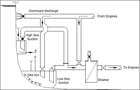
Figure 79 - De-icing returns on sea box and at strainer – section view
Text version: De-icing returns on sea box and at strainer – section view
A longitudinal cut view of a vessel's cooling system diagram. The sea box is the lowest suction entry to pump cool water through the engines' conduits. The overboard discharge is located close to the waterline and above the high sea suction entry, the latter used especially in shallow waters.
On the left, the waterline outside the ship's hull.
Overboard discharge conduit from the engines and valve shown just below the waterline.
Lower in middle section, the high sea suction box with valve and connecting conduit.
At bottom of the hull, the sea box and low sea suction with connecting valves and conduits leading to the strainer before continuing to engines.
Warning: Blockage of the sea boxes can cause the main engine cooling system to overheat, requiring reduced power to be used or the engine to be shut down completely.
Means must be provided to clear the sea bays if they do become blocked by ice. There are several design features that can ease operation or eliminate these problems:
- high and low inlet grilles can be provided as far apart as possible
- weir-type sea inlet boxes will overcome the problem of suction pipe clogging. The principle is commonly used in Baltic icebreakers and is shown in figure 80. The suction is separated from the sea inlet grilles by a vertical plate weir. Any ice entering the box can float to the top and is unlikely to be drawn back down to the suction level
- de-icing return(s) can be arranged to feed steam or hot water to the sea inlet box top, where frazil ice may have accumulated, or directly to the cooling system suction where a blockage may have occurred
- ballast water recirculation through the cooling water system allows ballast tanks to be used as coolers, alleviating any need to use blocked sea inlet boxes. It should be noted that, while this solution is effective, it is usually a short-term solution unless vast quantities of ballast water are available or if the vessel is fitted with shell circulation coolers because the recirculated ballast water will quickly become too warm for effective cooling
- means should be provided to clear the systems manually of blockage by ice
The mariners should be aware of these potential problems and the solutions available to them on their ship.
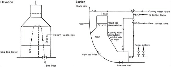
Figure 80 - Weir-type sea inlet arrangements
Text version: Weir-type sea inlet arrangements
Two simplified diagrams to quickly visualize how valves and conduits function in the Weir-type sea inlet arrangements when recirculating cold water in and out the vessel when ice forms in the system.
Elevation: describes the sea box outlet, where water enters via the bottom sea inlet. It circles back to the sea box via the return valve.
Section: describes the ship's side showing the waterline. Underwater there is the “Weir” with vent above that waterline to allow frazil ice accumulation here instead than going into the system's conduits. The cooling water is recirculated to the inlet side of the Weir. This Weir is connected either to the high or low sea inlet. The Weir connects via valves to the pump suctions, ballast tanks, engines conduits.
5.5.2 Freezing of piping, valves and tanks
Water in pipes, valves, and tanks may freeze making it impossible to empty bilges and ballast tanks, which may also result in structural damage. Fore Peak and After Peak ballast tanks are particularly vulnerable to freezing as they are often exposed to the ambient air temperature, being mostly above the waterline. Wing ballast tanks extending above the waterline are also vulnerable to freezing, and any ballast tank filled with fresh water will freeze more quickly than if containing sea water. If ballast tanks are pressed-up, with any standing water in the air vent pipes and sounding pipes, these pipes may freeze, preventing the ballast from being pumped. The vessel design should ensure that freezing is minimized or eliminated by judicious arrangement of the tanks and piping, and selection of valves and heating systems. When the vessel is scheduled to encounter very cold air temperatures every effort should be made to strip tanks and lines in which freezing may occur.
Warning: Water can freeze in bilge and ballast lines and cause structural damage in tanks.
The fire-fighting system is often exposed to the environment and must be available when required. Options to have the fire fighting system available include:
- draining the fire-main system gives the best protection from freezing, but may not always be possible
- drying the fire-main system under air pressure
- filling the fire-main system with a fluid of low freezing point (such as glycol and water); however, this is the least practical option
- allowing the fire-main to flow continuously overboard to maintain circulation; however, this is recommended only for comparatively short-term operation because of the build-up of ice at the overflow points where hydrants have been left open
Hydraulic deck machinery such as windlasses, winches, cranes, boat davits etc. can also be affected by extreme cold. The hydraulic fluid tanks, pumps and piping should be located in heated internal areas of the vessel in proximity to the machinery for which they provide the power.
The mariners must be aware of these potential problems and the solutions available to them on their ship.
5.5.3 Waste disposal
All vessels produce waste, including: contaminated water ballast, waste oil, domestic garbage, and human wastes. These wastes must be safely and efficiently disposed of, or retained on board, until they can be discharged ashore.
Under the Arctic Shipping Safety and Pollution Prevention Regulations, any discharge into the sea of oil, oily mixtures, noxious liquid substances or mixtures containing such substances from any vessel is prohibited.
Discharges of sewage within polar waters are prohibited except when performed in accordance with MARPOL Annex IV at a minimal distance of 3 NM from ice shelf or fast ice and as far as practicable from areas of ice concentration exceeding 1/10. Other exceptions can be applicable.
Discharge of garbage into the Arctic sea is forbidden except under permission in accordance with regulation 4 of MARPOL Annex V.
Warning: Any discharge into the sea of oily or noxious liquid substances mixtures will contravene with the Polar Code.
5.5.4 Fuel oil heating
On vessels that use heavy or intermediate fuel for the main engine it is normal for the fuel to be heated in the main bunker tanks. Steam heating coils are conventional, but thermal fluid may also be used. These coils usually are sized to deal with the low temperatures experienced during Arctic or cold water operations and a temperature control is provided to protect against over-heating. However, great care should be taken to ensure that, when moving into more temperate areas, the fuel oil heating system is not over-heating.
Warning: Make sure that the fuel oil heating system is not over-heating when the vessel moves into more temperate areas
- Date modified: