
Ice Navigation in Canadian Waters
Chapter 4: Navigation in ice covered waters
Table of Contents
- Preface
- Chapter 1: Icebreaking and Shipping Support Services
- Chapter 2: Regulations and Guidelines
- Chapter 3: Ice Climatology and Environmental Conditions
- Chapter 4: Navigation In Ice Covered Waters
- Chapter 5: Vessel Design and Construction for Ice Operations
- Annex I: Terminology for Ice, Navigation and Vessel Design
- Annex II: Reference Material
Chapter 4: Navigation in ice covered waters
4.1 General
Ice is an obstacle to any vessel, even an icebreaker, and the inexperienced navigation officer is advised to develop a healthy respect for the latent power and strength of ice in all its forms. However, it is quite possible, and continues to be proven so, for well-found vessels in capable hands to navigate successfully through ice-covered waters.
The first principle of successful ice navigation is to maintain freedom to manoeuvre. Once a vessel becomes trapped, the vessel goes wherever the ice goes. Ice navigation requires great patience and can be a tiring business with or without icebreaker escort. The open water long way round a difficult ice area whose limits are known is often the fastest and safest way to port, or to the open sea when leaving a port.
Experience has proven that in ice of higher concentrations, 4 basic vessel handling rules apply:
- keep moving - even very slowly, but try to keep moving
- try to work with the ice movement and weaknesses but not against them
- excessive speed almost always results in ice damage
- know your vessel’s manoeuvring characteristics
Warning: excessive speed is the major cause of damage to vessels by ice.
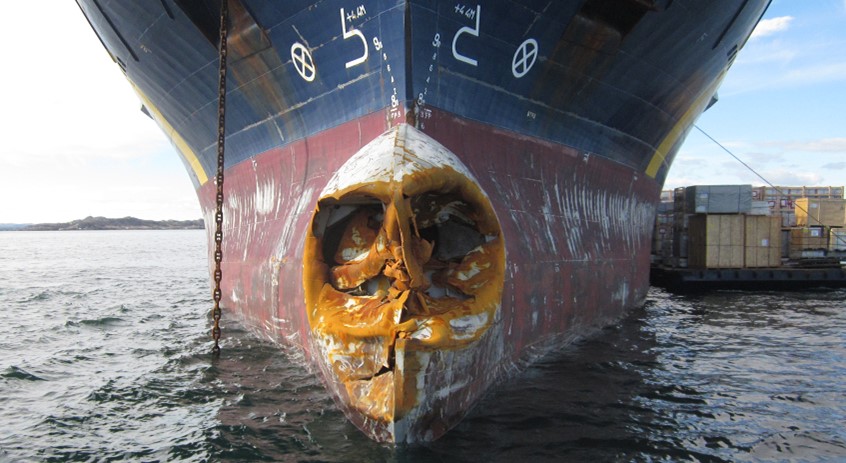
Figure 42 - Bulbous bow of M/V Zélada Desgagnés damaged by ice in Frobisher Bay July 2012Footnote 9
4.2 Requirements for vessels operating in ice
The propulsion plant and steering gear of any vessel intending to operate in ice must be reliable and must be capable of a fast response to manoeuvring orders. The navigational and communications equipment must be equally reliable and particular attention should be paid to maintaining radar at peak performance.
Light and partly loaded vessels should be ballasted as deeply as possible, but excessive trim by the stern is not recommended, as it cuts down manoeuvrability and increases the possibility of ice damage to the more vulnerable lower area of the exposed bow. Engine room suction strainers should be able to be removed easily and to be kept clear of ice and snow. Good searchlights must be available to aid in visibility during night navigation with or without icebreaker support.
Vessels navigating in ice-covered waters may experience delays and, therefore, should carry sufficient fresh water, supplies and manoeuvring fuel, especially vessels which use heavy bunker fuel for main propulsion.
4.3 Adverse environmental conditions
Vessels and their equipment at sea in Canadian winters and in high latitudes are affected by the following:
- low surface temperatures
- high winds
- low sea-water injection temperatures
- low humidity
- ice conditions ranging from slush ice to solid pack
- snow, sleet, and freezing rain
- fog and overcast, especially at the ice/water interface, and
- superstructure icing when there is the great and dangerous possibility of heavy and rapid icing with consequent loss of stability
4.3.1 Superstructure icing
Superstructure icing is a complicated process which depends upon meteorological conditions, condition of loading, and behaviour of the vessel in stormy weather, as well as on the size and location of the superstructure and rigging. The more common cause of ice formation is the deposit of water droplets on the vessel's structure. These droplets come from spray driven from wave crests and from vessel-generated spray. Ice formation may also occur in conditions of snowfall, sea fog, (including Arctic sea smoke) a drastic fall in ambient temperature, and from the freezing of raindrops on contact with the vessel's structure. Ice formation may sometimes be caused or accentuated by water shipped on board and retained on deck.
Vessel icing is a function of the vessel's course relative to the wind and seas and generally is most severe in the following areas: stem, bulwark and bulwark rail, windward side of the superstructure and deckhouses, hawse pipes, anchors, deck gear, forecastle deck and upper deck, freeing ports, containers, hatches, aerials, stays, shrouds, masts, spars, and associated rigging. It is important to maintain the anchor windlass free of ice so that the anchor may be dropped in case of emergency. Constant spray entering the hawse pipes may freeze solid inside the pipe, also anchors stowed in recessed pockets may freeze in place, both conditions preventing letting the anchor go. It is good practice in freezing spray to leave anchors slightly lowered in the hawse pipe in order to free them from ice accretion when needed. It is also advisable to maintain securing claws in place in case of slippery brakes, so that the anchors can be readily released in the event of a power blackout.
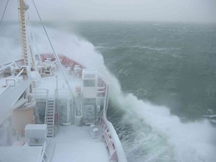
Figure 43 - Severe icing conditions (CCG)
Superstructure icing is possible whenever air temperatures are -2.2 °C or less and winds are 17 knots or more. It is very likely to take place when these conditions occur at the same time.
In fresh water such as the Great Lakes and St. Lawrence River superstructure icing will occur at 0 °C and below, and accumulate faster than in salt water conditions.
Generally speaking, winds of Force 5 on the Beaufort scale may produce slight icing; winds of Force 7, moderate icing; and winds of above Force 8, severe icing.
Under these conditions, the most intensive ice formation takes place when wind and sea come from ahead. In beam and quartering winds, ice accumulates more quickly on the windward side of the vessel, thus leading to a constant list which is extremely dangerous as the deck-immersion point could easily be reached with a loaded vessel.
Warning: Vessel icing may impair the stability and safety of a vessel.
The effects of freezing spray can be minimized by slowing down in heavy seas to reduce bow pounding, running with the sea, or seeking more sheltered sea conditions near-shore or in sea ice. Another option may be to head to warmer waters, although this is not possible in many Canadian marine areas.
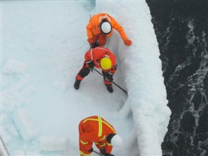
Figure 44 - Crew removing ice from bulwarks
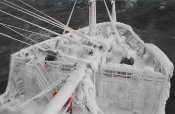
Figure 45 - Ice build-up on forecastle
Under severe icing conditions, manual removal of ice may be the only method of preventing a capsize. It is important for the mariner to consider the predicted duration of an icing storm and the rate at which ice is accumulating on his vessel in determining which strategy to follow.
Several tips for minimizing icing hazards on fishing vessels are:
- head for warmer water or a protected coastal area
- place all fishing gear, barrels, and deck gear below deck or fasten them to the deck as low as possible
- lower and fasten cargo booms
- cover deck machinery and boats
- fasten storm rails
- remove gratings from scuppers and move all objects which might prevent water drainage from the deck
- make the vessel as watertight as possible
- if the freeboard is high enough, fill all empty bottom tanks containing ballast piping with sea-water, and
- establish reliable two-way radio communication with either a shore station or another vessel
Freezing spray warnings are included in marine forecasts by ECCC. However, it is difficult to provide accurate icing forecasts as individual vessel characteristics have a significant effect on icing. Graphs assessing the rate of icing based on air temperature, wind speed, and sea-surface temperature can provide a guide to possible icing conditions, but should not be relied on to predict ice accumulation rates on a vessel. Caution should be exercised whenever gale-force winds are expected in combination with air temperatures below -2 °C.
4.4 Signs of ice in the vicinity
When steaming through open water, it may be possible to detect the approach of ice by the following signs:
- Ice blink: this is a fairly reliable sign and may be the first indication that an ice field is in the vicinity. It can usually be seen for some time before the ice itself is visible and appears as a luminous reflection on the underside of the clouds above the ice. Its clarity is increased after a fresh snowfall. On clear days, ice blink is less apparent but may appear as a light or yellowish haze which would indicate the presence of ice. Ice blink can sometimes be detected at night, either from the reflection of moonlight, or from the ambient starlight in clear weather.
- The sighting of small fragments of ice often indicates that larger quantities are not far away.
- Abrupt moderation of the sea and swell occur when approaching an ice field from leeward.
- In northern areas, and in Labrador and Newfoundland, the onset of fog often indicates the presence of ice in the vicinity.
On a clear day there may be abnormal refraction of light causing distortion in the appearance of features. Although the ice field will be seen at a greater distance than would normally be possible without refraction, its characteristics may be magnified out of all proportion – it may even appear as giant cliffs of ice in the far distance, with breaks between them where the open water lies.
The following are signs of open water:
- Water sky: dark patches on low clouds, sometimes almost black in comparison with the clouds, indicate the presence of water below them. When the air is very clear this indication is less evident. When iceblink is visible at night, the absence of blink in some sectors of the horizon may indicate open water but cannot be assumed to be water sky.
- Dark spots in fog give a similar indication, but are not visible for as great a distance as the reflection on clouds.
- A dark bank on a cloud at high altitude indicates the presence of patches of open water below, which could lead to larger areas of open water in the immediate vicinity.
Note: To accomplish effective ice management for the Grand Banks and Canadian eastern seaboard, it is imperative that sightings of ice and icebergs be reported to ECAREG CANADA through the nearest Canadian Coast Guard MCTS Centre. These messages will be handled free of charge.
4.5 Vessels navigating independently
Experience has shown that non-ice-strengthened vessels with an open water speed of about 12 knots can become hopelessly beset in heavy concentrations of relatively light ice conditions, whereas ice-strengthened vessels with adequate power should be able to make progress through first-year ice of 6/10 to 7/10 concentrations. Such vessels are often able to proceed without any assistance other than routing advice. In concentrations of 6/10 or less, most vessels should be able to steer at slow speed around the floes in open pack ice without coming into contact with very many of them.
4.5.1 Entering the ice
The route recommended by the Ice Superintendent through the appropriate reporting system i.e. ECAREG or NORDREG CANADA, is based on the latest available information and mariners are advised to adjust their course accordingly. The following notes on vessel-handling in ice have proven helpful:
- Do not enter ice if an alternative, although longer, open water route is available.
- It is very easy and extremely dangerous to underestimate the hardness of ice.
- Enter the ice at low speed to receive the initial impact; once into the pack, increase speed gradually to maintain headway and control of the vessel, but do not let the speed increase beyond the point at which she might suffer ice damage. Particular attention should be paid to applied power in areas of weak ice or open leads, pools, etc. where the speed might increase unnoticed to dangerous levels if power is not taken off.
- Be prepared to go “Full Astern” at any time.
- Navigation in pack ice after dark should not be attempted without high-power searchlights which can be controlled easily from the bridge; if poor visibility precludes progress, heave to in the ice and keep the propeller turning slowly as it is less susceptible to ice damage than if it were completely stopped, blocks of ice will also be prevented from jamming between the blades and the hull.
- Propellers and rudders are the most vulnerable parts of the vessel; vessels should go astern in ice with extreme care, and always with the rudder amidships. If required to ram ice when brought to a halt, vessels should not go astern into unbroken ice, but should move astern only in the channel previously cut by their own passage.
- All forms of glacial ice (icebergs, bergy bits, growlers) in the pack should be given a wide berth, as they are current-driven whereas the pack is wind-driven. Large features of old ice may be moving in a direction up-wind or across wind according to the direction of the current.
- Wherever possible, pressure ridges should be avoided and a passage through pack ice under pressure should not be attempted. The vessel may have to be stopped in the ice until the pressure event is ended.
- When a vessel navigating independently becomes beset, it usually requires icebreaker assistance to free it. However, vessels in ballast can sometimes free themselves by pumping and transferring ballast from side to side, and it may require very little change in trim or list to release the vessel, especially in high-friction areas of heavy snow-cover.
The mariner may wish to engage the services of an Ice Navigator in the Arctic.
4.6 Icebreakers
The CCG has a limited number of icebreakers available for the escort and support of shipping. These icebreakers are heavily committed and cannot always be provided on short notice when requested. Therefore, it is important for the ECAREG CANADA office or Ice Operations centre to be kept informed about the position and projected movements of vessels when ice is present. Failure to follow the reporting procedures, by vessels unsure of their ability to cope with prevailing ice conditions on their own, will only add to the difficulties of providing icebreakers and can lead to serious delays.
CCG icebreakers, many of which carry helicopters for ice reconnaissance, have operated in ice for many years, from the Great Lakes to as far north as the North Pole. Their Commanding Officers and crews are highly skilled and thoroughly experienced in the specialist fields of ice navigation, icebreaking, and ice escort. The fullest co-operation with the commanding officer of an icebreaker is, therefore, requested from a vessel or convoy under escort. For progress to be made, it is essential that escort operations be under the direction of the commanding officer of the icebreaker.
Note: No escort will be provided unless full co-operation is obtained.
4.6.1 Communicating with icebreakers
Once a vessel has requested icebreaker assistance, a radio watch should be kept on 2182 kHz and channel 16 very high frequency (VHF) (156.8 MHz). Difficulty is often experienced by icebreakers in making initial contact with these vessels, often with the result of lost time and extra fuel consumption. Medium frequency (MF) and VHF remain as proven communications tools and should be utilised to maintain contact with the icebreakers.
A continuous radiotelephone watch on an agreed frequency should also be maintained on the bridges of all vessels working with Coast Guard icebreakers. Vessels should be capable of working one or more of the following MF and VHF frequencies:
- 2237 kHz MF
- 2134 kHz MF
- 2738 kHz MF
- 156.3 MHz VHF channel 6
Table 9 lists the letter, sound, visual, or radiotelephony signals that are for use between icebreakers and assisted vessels. These signals are accepted internationally and they are restricted to the significance indicated in the table.
While under escort, continuous and close communications must be maintained. Communications normally will be by radiotelephone on a selected and mutually agreed inter-vessel VHF working frequency. It is vital to inform the Ice Operations centre and icebreaker of any change in the state of your vessel while awaiting an icebreaker escort.
Table 9 - Operational signals to be used to supplement radiotelephone communication between icebreaker and assisted vessel(s)
| Code Letters | Icebreaker Instruction | Assisted Vessel(s) Response |
|---|---|---|
| WM | Icebreaker support is now commencing. Use special icebreaker support signals and keep continuous watch for sound, visual, or radiotelephony signals | –n/a |
| A | Go ahead (proceed along the ice channel) | I am going ahead. (I am proceeding along the ice channel) |
| G | I am going ahead, follow me | I am going ahead. I am following you |
| J | Do not follow me. (proceed along the ice channel) | I will not follow you (I will proceed along the ice channel) |
| P | Slow down | I am slowing down |
| N | Stop your engines | I am stopping my engines |
| H | Reverse your engines | I am reversing my engines |
| L | You should stop your vessel instantly | I am stopping my vessel |
| 4 | Stop. I am icebound | I am stopping my vessel |
| Q | Shorten the distance between vessels | I am shortening the distance |
| B | Increase the distance between vessels | I am increasing the distance |
| Y | Be ready to take (or cast off) the tow line | I am ready to take (or cast off) the tow line |
| FE | Stop your headway (given only to a vessel in an ice channel ahead of an icebreaker) | I am stopping headway |
| WO | Icebreaker support is finished. Proceed to your destination | –n/a |
| 5 | Attention | Attention |
| E | I am altering my course to starboard | I am altering my course to starboard |
| I | I am altering my course to port | I am altering my course to port |
| S | My engines are going astern | My engines are going astern |
| M | My vessel is stopped and making no way through the water | My vessel is stopped and making no progress through the water |
Note: EMERGENCY STOP SIGNAL: Icebreakers have red revolving lights placed high up at the after end of the superstructure, visible from astern, also an icebreaking siren which both will be activated when an EMERGENCY STOP is required by the escorted vessel(s).
The signal “K” by sound or light may be used by an icebreaker to remind vessels of their obligation to listen continuously on their radios.
If more than 1 vessel is assisted (convoy), the distance between vessels should be as constant as possible; watch the speed of your own vessel and of the vessel ahead. Should the speed of your own vessel go down, give an attention signal to the vessel following.
The visual signals are seldom used in practice, but are listed in case voice radio communication fails.
Note: The use of these signals does not relieve any vessel from complying with the Convention on the International Regulations for Preventing Collisions at Sea, 1972 (COLREGs).
4.6.2 Report required before escort commences
Before escort or assistance commences, the icebreaker will require some or all of the following information to assess a vessel's capabilities while under escort in ice:
- vessel name, type and call sign
- Lloyds/IMO number
- owner/agent name
- country of registry
- tonnage (gross and net)
- vessel's length and beam
- port of departure and destination
- cargo type and amount (tonnage)
- ice navigator’s name, if embarked
- open water speed
- ice class (if any) and classification society
- drafts - forward and aft
- number of propellers and rudders
- shaft horsepower
- propulsion plant (whether diesel or turbine, and astern power expressed as a percentage of full ahead power) and the type of fuel for the main propulsion (for example, heavy bunker, diesel, LNG, etc.), and
- radiotelephone working frequencies, communications systems including telephone and/or fax number
Note: The onus is on the escorted vessel to advise the icebreaker of any deficiencies or restrictions that exist on their vessel. Per example, a combination of low-sulfur fuel and engine limiter under the Environmental Ship Index (ESI) can seriously impede the vessel’s ice navigation capacity, even under escort.
4.6.3 Icebreaking escort operations
The following are comments on aspects of icebreaker escort procedures:
- Track width: Progress through ice by an escorted vessel depends to a great extent on the width of the track made by the icebreaker, which is directly related to the speed of the forward progress of the icebreaker and the distance between the icebreaker and the vessel following.
- Icebreaker beam: When an icebreaker is breaking a track through large heavy floes at slow speed, the track will be about 30 to 40% wider than the beam of the icebreaker. At high speed, and if the ice is of a type which can be broken by the action of the stern wave (wake), the track may be as much as 3 times that of the icebreaker's beam.
- Minimum escort distance: The minimum distance will be determined by the commanding officer of the icebreaker on the basis of distance required by the escorted vessel(s) to come to a complete stop, after reversing to full astern from normal full ahead speed. Once this distance has been established, it is the responsibility of the vessel under escort to see that it is maintained. If the escorted vessel is unable to maintain the minimum escort distance and is falling back, the icebreaker must be informed at once to avoid the possibility of besetment and resulting delay.
- Maximum escort distance: Maximum distance is determined on the basis of ice conditions and the distance at which the track will remain open or nearly so. Increasing this distance creates the possibility of besetment, which would necessitate a freeing operation by the icebreaker. If the escorted vessel is unable to maintain the maximum escort distance, the icebreaker must be informed at once to avoid the possibility of besetment and resulting delay.
- Maintaining the escort distance: Mariners are requested to maintain the required escort distance astern of the icebreaker to the best of their ability. The progress made depends to a very great extent on the correct escort distance being maintained. This distance is dictated by the existing ice conditions and the risk of collision by the escorted vessel overtaking the icebreaker.
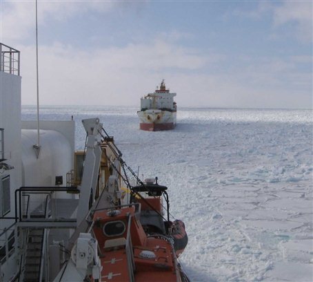
Figure 46 - The commanding officer of the icebreaker will determine a safe escort distance (CCG)
- Ice concentration: With 9+/10 concentrations, the track will have a tendency to close quickly behind the icebreaker, thus necessitating very close escort at a speed determined by the Commanding Officer of the icebreaker and the type of ice encountered.
- Ice pressure: When the ice concentration is 9+/10 and under pressure, the track will close very rapidly. Progress will be almost impossible because the track, being marginally wider than the beam of the icebreaker, will close and result in the escorted vessel becoming beset.
- Effect of escort on width of track: When an icebreaker makes a track, it causes outward movement of the floes. The width of the track depends on the extent of this outward movement together with the amount of open water available for floe movement. A longer escort distance allows a longer period of movement that results in a wider track.
-
Speed: When an icebreaker makes contact with ice floes on either side of the track, they may be forced outward with sufficient momentum to overcome the indraft at the stern; otherwise, some blocks and small floes will be drawn into the broken track. Most tracks made by icebreakers will contain ice rubble, which may also contain floes, which could damage an escorted vessel at excessive speed.
If an icebreaker proceeds at slow speed through ice, floes will slide along her hull and remain intact, with the exception of small pieces that may break away from the leading edges. At high speeds the floes will be shattered into many pieces. The icebreaker will, therefore, proceed at a speed which will break floes into as many pieces as possible, thus reducing the possibility of damage to the vessel following in the track.
- Escorted vessel beset: When a vessel under escort has stopped for any reason, the icebreaker must be notified immediately. If the vessel is beset, the engines should be kept slow ahead to keep the ice away from the propellers. The engines must be stopped only when requested by the icebreaker.
- Freeing a beset vessel: Freeing a vessel that has become beset during escort is usually carried out by the icebreaker backing down the track, cutting out ice on either bow of the beset vessel, and passing astern along the vessel's side before moving both vessels ahead. To free a vessel beset while navigating independently, the icebreaker will normally approach from astern and cross close ahead at an angle of 20 to 30 degrees to the beset vessel's course. Such an approach may be made on either side in moderate winds. In strong winds at a wide angle to the track, a decision as to which side the cross-ahead is made will be determined by which of the 2 vessels is more influenced by the wind. On occasion, the icebreaker may elect to pass down one side of the beset vessel, turn astern of her and pass up on the other side, thereby releasing pressure from both sides.
- Systems of escort: When a vessel becomes beset during escort, the normal procedure is for the icebreaker to back up to free her and then proceed ahead with the escorted vessel following. However, when progress is slow, the Free and Proceed system may be used, in which the beset vessel is directed to proceed up the track made by the icebreaker while backing up, the icebreaker then following behind. Before the escorted vessel reaches the end of the previously broken icebreaker track, the icebreaker proceeds at full speed to overtake and pass the escorted vessel. This cuts down the number of freeing operations and improves progress.
-
Red warning lights and air horn: When escorting vessels in ice, CCG icebreakers use 2 rotating red lights to indicate that the icebreaker has become stopped. In most cases these lights are placed in a vertical line 1.8 metres apart abaft the mainmast and are visible for at least 2 miles. However, construction restrictions of some icebreakers necessitate that these lights be placed horizontally in roughly the same aft-facing position.
As an additional warning signal, all icebreakers are fitted with and use a zet-horn, facing aft, audible up to 2 nautical miles, which sounds simultaneously with the red warning lights when they are activated. Prior to commencement of escort, all vessels will familiarize themselves with the positioning and operation of these red rotating lights and the zet-horn.
- Icebreaker stopped: Whenever the red revolving lights are displayed and the horn sounded, either separately or simultaneously, it signifies that the icebreaker has come to a standstill and is unable to make further progress without backing up. During close escort work, a lookout shall always be kept for the flashing red light. The mariner of the escorted vessel should treat these signals with extreme urgency and immediately reverse engines to full speed astern. The rudder should be put hard over to increase ice-friction on the hull as long as headway is carried, until all forward motion has ceased, then the rudder must be returned to the amidships position.
- Icebreaker stopping without warning: Mariners are cautioned that, because of unexpected ice conditions or in other emergency situations, the icebreaker may stop or otherwise manoeuvre ahead of the escorted vessel without these warning signals. Mariners must always be prepared to take prompt action to avoid overrunning the icebreaker.
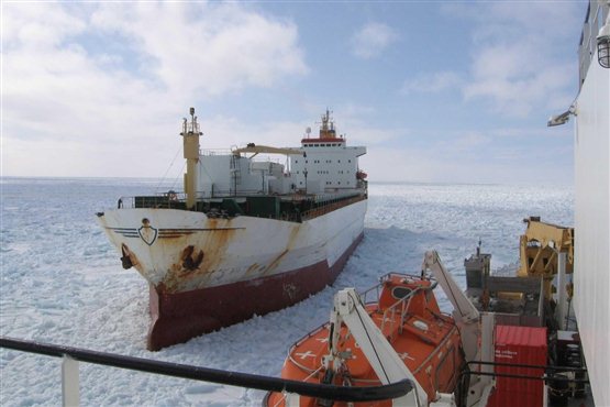
Figure 47 - Icebreaker backing alongside vessel to free it from the ice (CCG)
- Towing in ice: This procedure would only be undertaken in emergencies as there is an inherent risk of damage to both vessels. The commanding officer of an icebreaker who receives a request for a tow will judge whether or not the situation calls for such extreme measures. CCG icebreakers are not equipped for close-coupled towing operations.
- Anchoring in ice: Anchoring in the presence of ice is not recommended except in an emergency, but if such anchoring is necessary, only the minimum amount of cable/shackle should be used and the capstan/windlass should be available for immediate use. The engines must be on standby, or kept running, if the start-up time is more than 20 minutes. If the water is too deep to let go an anchor, the vessel may be stopped in fast ice (when the conditions permit). When off-shore in deep water, a vessel can usually safely stop in the drift ice without an anchor down when darkness or poor visibility prevents further progress. The vessel will then drift with the ice and may be turned around by the ice, but will be quite safe if properly placed before shutting down.
-
Convoys: Convoys of vessels may be formed by the commanding officer of the icebreaker, after consultation with the appropriate shore authority. During operations in ice, this action will best aid the movement of the maximum number of vessels when there are an insufficient number of icebreakers of suitable capacity available to facilitate the escort of vessels proceeding to or from adjacent areas or ports.
The commanding officer of the icebreaker will determine the order of station within the convoy, to be arranged to expedite the movement of the convoy through the ice (not necessarily on “first come-first served” basis). The vessels in the convoy are responsible for arranging and maintaining a suitable and safe distance between individual vessels. The icebreaker will designate the required distance to be maintained between itself and the lead vessel of the convoy.
If the ice conditions should change on route, or if some vessels have difficulty in following the vessel ahead, the Commanding Officer of the icebreaker may change the order of convoy station so that vessels within the convoy can assist the progress of others less capable than themselves.
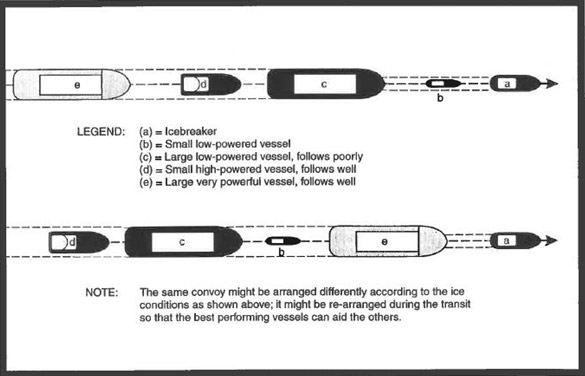
Figure 48 - Icebreaker escort – Ships in convoy (Courtesy of Marine Institute of Memorial University of Newfoundland: International Ice Navigator Course, March 31st, 1996)
Text version: Icebreaker escort – Ships in convoy
A diagram showing examples of icebreaking convoy arrangements.
Legend:
- = Icebreaker
- = Small low-powered vessel
- = Large low-powered vessel, follows poorly
- = Small high-powered vessel, follows well
- = Large very powerful vessel, follows well
1st example: The icebreaker in (a) leading the convoy is followed by all the vessels in order (b), (c), (d) and lastly (e).
2nd example: The order is (a), (e), (b), (c) and lastly (d).
Note: The same convoy might be arranged differently according to the ice conditions as shown above; it might be re-arranged during the transit so that the best performing vessels can aid the others.
4.7 Effect of ice and snow on vessel performance
Vessels not specifically designed and constructed for ice navigation must consider the suitability and best usage of their existing propulsion and control systems, in addition to hull strength, for navigation in ice-covered waters.
4.7.1 Vessel resistance
The resistance of a vessel is greater in level ice than in open water. As ice thickness and/or ice strength increases, the vessel must increase power to maintain its speed. However, even in open pack ice or in heavier ice concentrations, the navigator must use caution and avoid excessive speed.
In general it can be said that rafted, ridged, and rubbled ice present significant impediments to the progress of a vessel. Caution should also be used when navigating through level ice with occasional hummocks or rafted areas or inclusions of old ice.
Warning: Any vessel that is not strengthened for operating in ice should avoid large unbroken ice floes, particularly if the ice is deformed by rafts, ridges, or rubble.
When the ice thickness exceeds that in which the vessel can make continuous progress, (such as when the vessel encounters old ice, ridges, rafts, or hummocks), the vessel could resort to ramming if the vessel’s design and structural strength permits.
It is important that the ice navigator understands how much impact from the ice the vessel can withstand without suffering damage, and at what speed hull damage is likely to be inflicted by the ice environment currently being experienced.
The influence of snow on vessel performance varies directly with snow thickness and snow type, and greatly increases vessel resistance. The friction coefficient between snow and a vessel's hull varies with the consistency and wetness of the snow; wetter snow has a higher friction coefficient than dry snow. In certain environmental conditions the snow will be quite “sticky” whereas, in others, it will be very dry and brittle. One rule of thumb suggests that resistance from snow cover can be approximated by adding half the snow thickness to the observed ice thickness and assessing performance in ice of the increased calculated thickness. Resistance in “sticky” snow is very difficult to predict, but it can be very high: equal to, or greater than, the icebreaking resistance.
Low friction coatings and hull form are important elements in vessel performance in snow-covered ice. In ramming mode a low-friction hull coating will facilitate extraction astern after each ram, as well as permitting each ram to proceed further ahead than would be possible with a bare steel hull surface.
4.7.2 Vessel manoeuvring
The features of hull shape that influence manoeuvrability in ice to the greatest extent are length-to-breadth ratio, flare, mid-body, and bow and stern shape. Manoeuvrability is also greatly influenced by ice conditions, such as: thickness, coverage, pressure, and shear zone conditions. The diameter of a vessel's turning circle increases as the thickness of the ice increases. Turning in level ice conditions is generally influenced by the degree of confinement imposed by the surrounding ice. Steady turns are recommended for most vessels that are not as manoeuvrable as icebreakers, however it is more common for icebreakers to use star or channel breakout manoeuvres as a faster means of turning. Heeling systems have been demonstrated to be effective for most icebreaking vessels, especially in snow-covered ice situations.
4.7.3 Structural capability
A vessel's performance in ice can be limited by the hull structure's capability to withstand ice impacts. Different modes of operation and ice regimes will generate different magnitudes of ice impact forces. For example, a vessel encountering first-year ice will experience lower impact forces than a vessel encountering old ice. A vessel – usually an icebreaker - which is required to ram ice features aggressively with the intention of protecting less capable vessels or structures will, of necessity, incur higher impact forces to break ice which would damage that which they are protecting. In terms of overall magnitude, ramming operations generate the largest forces on the vessel's structure, and being repetitive, they may cause cumulative damage.
4.7.4 Performance Enhancing Systems
Performance enhancing systems are designed to reduce the power necessary for propulsion and to increase the vessel's manoeuvrability through ice. Heeling systems, which roll the vessel from side to side and reduce the effect of static friction, are helpful if the vessel is stuck in pressured ice, or beached on an ice feature. The following hull lubrication systems can also reduce resistance and aid manoeuvrability:
- Low friction coatings - Low friction coatings can be used to reduce drag forces and are now used on many icebreaking vessels.
- Air bubble system - The system uses 1 or more air compressors to force air through nozzles at the vessel's side below the waterline. The air bubbles rise to the surface together with entrained water, lubricating the interface between the ice and the vessel's hull, both above and below the waterline. The conditions and operations for which the system is particularly well-suited include: low speed transiting in “sticky ice” and ice with deep snow cover, manoeuvring in pressured ice, lubricating the hull during the break-away (extraction) portion of ramming, and manoeuvring alongside a dock. In open water situations the air bubblers can sometimes be used instead of thrusters.
- Water jet/air injection system - This system involves injecting air into water, which is pumped through nozzles at the vessel's side below the waterline.
- Water-wash system - The water-wash system pumps a large volume of water to nozzles at the bow above the water-line. The objective is to flood the ice with water, thereby lubricating the interface between vessel and ice, and to wash away any snow cover from the ice to be broken.
4.8 Vessel handling techniques in ice
4.8.1 Manoeuvres in different ice conditions
Ice is an obstacle to any vessel, even an icebreaker, and the inexperienced navigator is advised to develop a healthy respect for the potential strength of ice in all its forms. However, it is quite possible, and continues to be proven so, for well-maintained and well-equipped vessels in capable hands to navigate successfully through ice-covered waters. Mariners who are inexperienced in ice often find it useful to employ the services of an Ice Advisor for transiting the Gulf of St. Lawrence in winter or an Ice Navigator for voyages into the Arctic in the summer.
The first principle of successful ice navigation is to avoid stopping or becoming stuck in the ice. Once a vessel becomes trapped, it goes wherever the ice goes. Ice navigation requires great patience and can be a tiring business, with or without icebreaker escort. The longer open water way around a difficult ice area whose limits are known is often the fastest and safest way to port or to reach the open sea.
Note: Do not underestimate the hardness of ice and its potential for inflicting damage.
4.8.1.1 Before entering the ice
For an unstrengthened vessel, or for a vessel whose structural capability does not match the prevailing ice conditions, it is preferable and safer to take any alternative open water route around the ice even if it is considerably longer. An open water route is always better than going through a large amount of ice. Any expected savings of fuel will be more than offset by the risk of damage, and the actual fuel consumption may be higher by going through ice, even if the distance is shorter.
The following conditions must be met before a vessel enters an ice field:
- Follow the route recommended by the Ice Office via the MCTS. This route is based on the latest available information and Mariners are advised to adjust their course accordingly if changes are recommended during the passage.
- Extra lookouts must be posted and the bridge watch may be increased, depending on the visibility.
- There must be sufficient light to complete the transit of the ice field in daylight or the vessel must be equipped with sufficient high-powered and reliable searchlights for use after dark.
- Reduce speed to a minimum to receive the initial impact of the ice.
- The vessel should be at right angles to the edge of the pack ice at entry to avoid glancing blows and the point of entering the ice must be chosen carefully (see figure 49), preferably in an area of lower ice concentration.
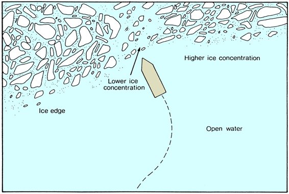
Figure 49 - Correct approach to ice field: reduced speed and perpendicular to edge (Courtesy of Capt. George Q. Parnell “Ice Seamanship”)
Text version: Correct approach to ice field: reduced speed and perpendicular to edge
Depiction of how a vessel in open water should approach perpendicularly ice fields, also by aiming for lower ice concentrations and reducing speed before re-adjusting power and direction to incoming leads within the ice fields.
- The engine room personnel must be briefed fully as to the situation and what may be required of them, as it may be necessary to go full astern at any time, and engine manoeuvres will be frequent as speed is constantly adjusted.
- The vessel must be ballasted down to ice draft, if appropriate, or to such a draft that would offer protection to a bulbous bow, rudder, or propeller (as applicable).
- The vessel should be fitted with an internal cooling system for use in the event that the main engine cooling water intake becomes clogged with slush ice.
4.8.1.2 After entering the ice
Once the ice is entered, speed of the vessel should be increased slowly, according to the prevailing ice conditions and the vulnerability of the vessel. If visibility decreases while the vessel is in the ice, speed should be reduced until the vessel can be stopped within the distance of visibility. If in doubt, the vessel must stop until the visibility improves. The potential of damage by ice increases with less visibility. If the vessel is stopped, the propeller(s) should be kept turning at low revolutions to prevent ice from building up around the stern.
When navigating in ice, the general rules are:
- use the pack to its best advantage. Follow open water patches and lighter ice areas even if initially it involves large deviations of course
- in limited visibility, beware following an open water lead at excessive speed, it may be the trail of an iceberg
Do not allow the speed to increase to dangerous levels when in leads or open pools within an ice field, or when navigating open pack conditions.
4.8.1.3 Turning in ice
Changes in course will be necessary when the vessel is in ice. If possible course changes should be carried out in an area of open water or in relatively light ice, as turning in ice requires substantially more power than turning in water, because the vessel is trying to break ice with its length rather than with its bow, turns should be started early and make as wide an arc as possible to achieve the new heading. Care must be taken even when turning in an open water area, as it is easy to underestimate the swing of the vessel and to make contact with ice on the vessel's side or stern: a glancing blow with a soft piece of ice may result in the vessel colliding with a harder piece (see figure 50).
The vessel will have a strong tendency to follow the path of least resistance and turning out of a channel may be difficult or even impossible. Vessels that are equipped with twin propellers should use them to assist in the turn. In very tight ice conditions, a vessel sailing independently may make better progress by applying full power and leaving the rudder amidships This allows her to find the least resistance without any drag from the rudder in trying to maintain a straight course by steering.
Warning: Avoid turning in heavy ice – seek lighter ice or open water pools.
If it is not possible to turn in an open water area, the mariner must decide what type of turning manoeuvre will be appropriate. If the turn does not have to be sharp then it will be better to maintain progress in ice with the helm over. When ice conditions are such that the vessel's progress is marginal, the effect of the drag of the rudder being turned may be sufficient to halt the vessel's progress completely. In this case, or if the vessel must make a sharp turn, the star manoeuvre will have to be performed. This manoeuvre is the equivalent of turning the vessel short round in ice by backing and filling with the engine and rudder. Mariners will have to weigh the dangers of backing in ice to accomplish the star manoeuvre, against any navigational dangers of a long turn in ice. Care must be taken while backing on each ram that the propeller and rudder are not forced into unbroken ice astern.
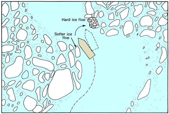
Figure 50 - Danger in turning in an ice channel (Courtesy of Capt. George Q. Parnell “Ice Seamanship”)
Text version: Danger in turning in an ice channel
Depiction of how a vessel navigating in ice fields must be aware of dangers presented by harder ice floes, especially if the vessel is pushed off by other softer floes while following open water leads.
4.8.1.4 Backing in ice
Backing in ice is a dangerous manoeuvre as it exposes the most vulnerable parts of the vessel, the rudder and propeller, to the ice. It should only be attempted when absolutely necessary and in any case the vessel should never ram astern. In recent years “double-acting” ice strengthened vessels have been developed which are designed to break ice while moving astern in order to protect their bulbous bows, but only this type of specially designed vessel should attempt such manoeuvres.
The vessel should move at dead slow astern and the rudder must be amidships (figure 51). If the rudder is off centre and it strikes a piece of ice going astern, the twisting force exerted on the rudder post will be much greater than if the rudder is centred. In the centre position, the rudder will be protected by an ice horn if fitted.
If ice starts to build up under the stern, a short burst of power ahead should be used to clear away the ice. Using this technique of backing up to the ice and using the burst ahead to clear the ice can be very effective, but a careful watch must be kept of the distance between the stern and the ice edge. If a good view of the stern is not possible from the bridge, post a reliable lookout aft with access to a radio or telephone.
Warning: Avoid backing in ice whenever possible. If you must move astern, do so with extreme caution at dead slow.
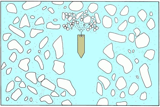
Figure 51 - Backing onto Ice: Rudder Amidships Dead Slow Astern (Courtesy of Capt. George Q. Parnell “Ice Seamanship”)
Text version: Backing onto Ice: Rudder Amidships Dead Slow Astern
Depiction of how a vessel should always keep its rudder amidships while moving backwards in ice floes as to prevent potential damage to its primary steering system.
4.8.1.5 Precautions to avoid becoming beset
The easiest way to avoid being beset is to avoid areas of ice under pressure. Ice can be put under pressure in several ways. The most common pressure situation occurs when open pack ice closes because of prevailing winds, but it may also occur when tides, currents, or on-shore breezes blow ice onto the shore.
Pack ice that has been under pressure for some time will deform, overriding as rafts or piling up as ridges or hummocks. Appearances are deceiving as the sail on a ridge or hummock may be only 1 to 2 metres above the ice cover but the keel could be several metres below.
Warning: Any vessel that is not strengthened for operating in ice should avoid floes that are rafted or ridged.
The danger from becoming beset is increased greatly in the presence of old or glacial ice, as the pressure on the hull is that much greater.
When in pack ice, a frequent check should be made for any signs of the track closing behind the vessel. Normally there will be a slight closing from the release of pressure as the vessel passes through the ice, but if the ice begins to close up completely behind the vessel it is a strong sign that the pressure is increasing (figure 52).
Similarly, if proceeding along an open water lead between ice and shore, or ice in motion and fast ice, watch for a change in the wind direction or tide as the lead can close quickly.
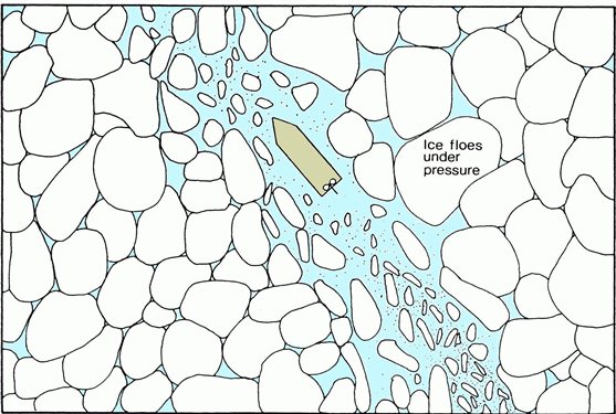
Figure 52 - Pressure in ice field closes track behind vessel (Courtesy of Capt. George Q. Parnell “Ice Seamanship”)
Text version: Pressure in ice field closes track behind vessel
Depiction of how a vessel's track in ice reacts to pressure within the ice field.
4.8.1.6 Freeing a beset vessel
To free a beset vessel, it may be necessary to wait for conditions to improve or it is necessary to loosen the grip of ice on the hull, which may be accomplished in several ways:
- Go ahead and astern at full power while alternating the helm from port to starboard, which has the effect of levering the ice aside. Care must be taken when going astern to ensure that no ice goes through the propeller(s), or if the vessel frees itself that it does not make sternway into any heavy ice. In vessels with twin propellers, they should be alternated with one ahead and one astern for a few minutes, then each changed to the opposite direction, slewing the stern from side to side to create a wider opening in the ice astern.
- Alternate the ballast to port and to starboard to list the vessel and change the underwater shape. This method should only be done with knowledge of the possible consequences of an exaggerated list if the vessel comes free quickly.
- Alternate filling and emptying of the fore and after peak tanks is a safer manoeuvre than using the ballast tanks, but it is usually only effective in changing the trim for the bow to get a better angle of attack on the ice ahead, or for the propellers to be given a better grip by greater submersion. It can also be effective in extracting from a ridge, by raising the bow so that the vessel slides backwards as the bow is raised.
- In smaller vessels it may be possible to swing weights over the side suspended on the vessel's cranes or lifting gear to induce a list and break the vessel free. This method should only be used with knowledge of the possible consequences if the vessel comes free quickly (see (b) above).
Figure 53 - Ice under pressure will close the track behind the vessel (CCG)
4.8.1.7 Ramming
Ramming is particularly effective when attempting progress through ice that is otherwise too thick to break continuously.
Warning: Ramming should not be undertaken by vessels that are not ice-strengthened or by vessels with bulbous bows. Ice-strengthened vessels, when undertaking ramming, should do so with extreme caution.
For vessels that can ram the ice it is a process of trial and error to determine the optimum distance to back away from the ice edge to build up speed. The optimum backing distance will be that which gives the most forward progress with the least travel astern. It is always necessary to start with short rams to determine the thickness and hardness of the ice. All vessels must pay close attention to the ice conditions, to avoid the possibility of lodging the vessel across a ridge on a large floe. Floes of old ice which may be distributed throughout the pack in northern waters, must be identified and avoided while ramming.
Ramming must be undertaken with extreme caution because the impact forces caused when the vessel contacts the ice can be very high. For ice-strengthened vessels these forces may be higher than those used to design the structure and may lead to damage. However, if the ramming is restricted to low speeds, the risk of damage will be greatly reduced.
4.8.2 Handling a damaged vessel in ice
Abandoning vessel in ice-covered waters is possible, if necessary, by landing lifeboats or life rafts on the ice, if the ice is thick enough to take their weight. Vessels fitted with quick-release drop-lifeboats without davits should never attempt to launch them into ice, but should lower them gently to the ice-surface by using the recovery equipment in reverse.
If the vessel can be made sufficiently seaworthy to proceed, an assessment will have to be made of the demands that will be placed on the vessel by breaking ice during the remainder of the voyage, as opposed to any risks in waiting for escort. The damaged area should be protected from further impacts by trimming the vessel, although this will have an effect on its ability to break ice. In ice-strengthened vessels, ballasting to minimize flooding can expose the hull above or below the ice belt. Care should be taken that the change in trim does not expose the rudder and propeller(s) to the ice, but, if it is unavoidable, that any subsequent decision is made with the knowledge of this exposure.
4.8.3 Berthing
Berthing in ice-covered waters can be, and usually is, a long process, particularly in the Arctic where normally there are no tugs. When approaching a berth in ice-covered waters it is desirable (even if this is not the normal practice) to have an officer stationed on the bow to call back the distance off the wharf or pier because a variation in ice thickness (not observed from the bridge) can result in a sudden increase or decrease in the closing speed of the bow and the wharf.
There are a multitude of considerations depending on vessel size and berth type, but the aim should be to bring the vessel alongside with as little ice as possible trapped between the vessel and the dock face. It may be accomplished by landing the bow on the near end of the dock and sliding along the face (similar to landing the bow on the wall entering a lock in the Seaway), or by bringing the bow in to the desired location, passing a stout spring line, and going ahead slowly so that the wash flushes the ice out from between the dock and the vessel (figure 54). Frequently it is necessary to combine the two techniques (in vessels of sufficient manoeuvrability it is possible to clear ice away from the wharf prior to berthing). Care must be exercised not to damage the wharf by contact with the vessel, or by forcing ice against pilings. The vessel itself can be damaged by forcing unbroken floes of hard ice against the unyielding facing of a solid berth.
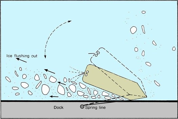
Figure 54 - Berthing: Flushing out ice with wash while bow is fixed with a spring line (Courtesy of Capt. George Q. Parnell “Ice Seamanship”)
Text version: Berthing: Flushing out ice with wash while bow is fixed with a spring line
Depiction of how a vessel conduct "flushing out" maneuvers using its spring line secured to the dock as to reduce the amount of ice between its hull and the dock for ideal mooring.
Once the vessel is secured, all efforts must be made to keep the vessel alongside and not to allow ice to force its way between the vessel and the dock. If the dock is in a river or in a strong tidal area there is nothing that will keep the vessel alongside if the ice is moving. The prudent thing to do is to move the vessel off the dock before the situation deteriorates. The ice conditions can change quickly when alongside a wharf and, for this reason, it is desirable to keep the engine(s) on standby at all times.
Warning: Keep the engine(s) on standby at river berths or strong tidal areas where ice is in motion
4.8.4 Towing in ice
Towing in ice on a long wire is possible, although the strain on the tow line is much greater than in an open water tow as the tug or icebreaker is subject to the sudden acceleration/deceleration of icebreaking. The situation can be alleviated somewhat if there is an icebreaker making a track ahead of the towing icebreaker. The CCG does not usually engage in towing operations except in emergency situations. There is a long tradition of this sort of work in the Baltic, though, where icebreakers are specially designed with a notch in the stern and heavy winches and cables to enable the bow of the towed vessel to be brought up against the stern of the icebreaker and secured. This towing method is known as close coupled towing and is considered an efficient method of towing in uniform ice conditions.
Warning: Close-coupled towing techniques which are commonly used by European icebreakers in the Baltic Sea and in Russian waters of the Northern Sea Route, are not commonly used in Canadian waters
Towing in ice was common in the 1970s and early 1980s in the Beaufort Sea, by anchor-handling supply boats or icebreakers when repositioning drill vessels and platforms. Experience has shown that towing in ice requires specialized skills in towing and ice navigation, coupled with appropriate purpose-designed equipment. The towing equipment must be robust and must allow frequent changes in towline length. The use of shock-absorbing springs or heavy surge chains is recommended. Bridle arrangements must optimise manoeuvrability to allow the towing vessel and tow to be navigated around heavy ridges and ice floes.
It is the recommended practice that the connection between vessels should incorporate a weak link, usually a lighter pendant, which will fail before the tow-line or bridle. In difficult ice conditions the towline should be kept as short as possible to avoid having the towing-wire pass under the ice floes, due to the weight of the wire and the catenary formed by a longer line. In freeing a beset tow, the towing vessel can shorten the tow-line to provide some propeller wash to lubricate the tow, but care must be exercised to avoid damaging the tow with heavy ice wash. Towing in ice is a special application not to be undertaken without the benefit of training and experience.
4.8.5 Speed
In all attempts at manoeuvring or avoiding ice, it must be remembered that the force of impact varies as the square of the speed. Thus, if the speed of the vessel is increased from 8 to 12 knots, the force of impact with any piece of ice has been more than doubled. Nevertheless, it is most important when manoeuvring in ice to keep moving. The prudent speed in a given ice condition is a result of the visibility, the ice type and concentration, the ice class, and the manoeuvring characteristics of the vessel (how fast it can be stopped).
4.8.6 Ice management
In situations where an icebreaker is used to prevent ice from colliding with fixed structures, such as drilling platforms, the technique of ice management comes into force. The icebreaking and offshore supply fleet in the Canadian and U.S. Arctic has been involved with work to support drilling operations. Icebreakers either try to break up drifting ice before it arrives at the structure or to push and divert the dangerous floes out of the way so that they by-pass the structure. In ice management, obtaining information about the present and predicted ice conditions is very important, to ascertain the best deployment of the icebreakers.
4.9 Close-range ice hazard detection
Although a careful lookout will help the vessel avoid large ice hazards (such as icebergs), there is still a need for the close-range detection of ice hazards, such as small icebergs and old ice floes. Close-range ice navigation is an interactive process, which does not lend itself to traditional passage planning techniques.
Two groups of equipment aid in close-range hazard detection: visual (searchlights and binoculars) and radar (both X- and S-band marine radars and the newer enhanced ice radar systems).
4.9.1 Use of radar for ice detection
Radar can be a great asset in ice navigation during periods of limited visibility, but only if the display is properly interpreted. Ice makes a poor radar target beyond 3 to 4 nautical miles and the best working scale is in the 2 to 3 nautical mile range. Radar signal returns from all forms of ice (even icebergs) are much lower than from vessel targets, because of the lower reflectivity of radar energy from ice, and especially snow, than from steel. Detection of ice targets with low or smooth profiles is even more difficult on the radar screen, although the radar information may be the deciding factor when attempting to identify the location of these targets under poor conditions, such as in high seas, fog, or in heavy snow return. For example, in close ice conditions the poor reflectivity and smooth surface of a floe may appear on the radar as a patch of open water, or signal returns from sea birds in a calm sea can give the appearance of ice floes. In an ice field, the edge of a smooth floe is prominent, whereas the edge of an area of open water is not. The navigator must be careful not to become over-confident in such conditions.
In strong winds the wave clutter in an area of open water will be distributed uniformly across the surface of the water, except for the calm area at the leeward edge.
Ice within 1 mile of, and attached to, the shore may appear on the radar display as part of the land itself. The operator should be able to differentiate between the 2 if the receiver gain is reduced. Mariners are advised not to rely solely on radar for the detection of icebergs because they may not appear as clearly defined targets. In particular, mariners should exercise prudence when navigating in the vicinity of ice or icebergs. The absence of sea clutter also may indicate that ice is present. Although ridges may show up well on the radar display, it is difficult to differentiate between ridges, closed tracks of vessels and rafted ice, as all have a similar appearance on radar.
The effectiveness of marine radar systems will vary with power and wavelength. The optimum settings for the radar will be different for navigating in ice than for open water. As the radar reflectivity of ice is much lower than for vessels or land, the gain will have to be adjusted to detect ice properly. Generally, high-power radars are preferred and it has been found that radars with 50 kW output provide much better ice detection capability than 25 kW radars. Similarly, 3‑centimetre radars (x-band) provide better ice detail while 10‑centimetre radars (s-band) show the presence of ice and ridging at a greater distance - it is therefore recommended that both wavelengths be used.
Warning: Marine radar provides an important tool for the detection of sea ice and icebergs. However, do not rely solely on your radar in poor visibility as it is not certain that radar will detect all types and sizes of ice and it will not differentiate old ice from first year ice.
4.9.2 Ice navigation radars
Conventional marine radars are designed for target detection and avoidance. Enhanced marine radars provide a higher definition image of the ice that the vessel is transiting through and may help the user to identify certain ice features. There are various shipboard marine radar systems enhanced and optimized for ice navigation. Figures 55 to 58 compare images from a conventional x-band radar and an enhanced x-band ice navigation radar used on board a CCG icebreaker. In the ice navigation radar, the analog signal from the x‑band radar (azimuth, video, trigger) is converted by a modular radar interface and displayed as a 12-bit digital video image (1024x1024).
In the enhanced marine radar, the coastline is more clearly defined; icebergs are visible at greater distances, as are the smaller bergy bits and growlers. In the standard radar, sea clutter affects the ability to see smaller targets near the vessel. X-band radars will produce clearer images of the ice at short ranges, such as under 4 nautical miles, when set to a short pulse. The shapes of ice floes, the ridges and rafted ice and open water leads are also more distinct in an ice navigation radar, particularly when using the short radar pulse length.
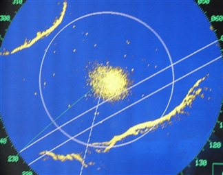
Figure 55 - Standard X-band Radar Image (Source: CCG)
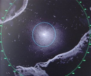
Figure 56 - Enhanced X-band Radar Image (Source: CCG)
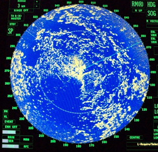
Figure 57 - Standard X-band Radar Image (Source: CCG)
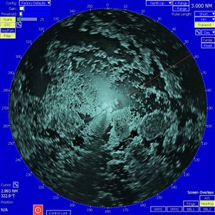
Figure 58 - Enhanced X-band Radar Image (Source: CCG)
Experiments with cross-polarized radar have demonstrated that it is possible to enhance radar displays for better detection of old and glacier ice. Advances are also being made in shipboard systems which use passive microwave radiometers to measure the natural emissivity of the ice (the relative ability of its surface to emit energy by radiation), producing radar-like displays which may be colour-enhanced to distinguish between open water and various ice types.
4.9.3 Iceberg detection
Icebergs normally have a high freeboard and, as such, they are easy to detect visually (in clear conditions) and by vessel's radar. In poor to no visibility, radar must be relied upon. The radar return from an iceberg with low freeboard, smooth surface, or deep snow cover is less obvious, particularly if surrounded by bright returns from sea or ice clutter. Depending upon their size, aspect and attitude, icebergs may be detected at ranges between 4 and 15 nautical miles or even further for very large high profile icebergs, detection ranges diminishing in fog, rain, and other conditions affecting the attenuation of radar return. Icebergs may not appear as clearly defined targets but the sector of the radar display directly behind the iceberg may be free of clutter. Iceberg radar targets will sometimes cause a “radar shadow” on the far side, in which other targets will not show. It is sometimes possible to identify an iceberg target lost in the clutter by this shadow extending away from the observer. A large iceberg with a long and gently sloping aspect may not provide enough reflective surfaces to show at all on radar, so it should never be assumed that just because there are no targets in view there are no icebergs around.
Warning: Do not rely solely on marine radar to detect ice, particularly glacial ice.
Observation will reveal the shadow to increase in size on approach to the iceberg, and to swing around as the angle between the vessel and the iceberg changes. However, care should be taken in using this technique as the returns from pack ice can obscure the return from the iceberg.
As the vessel gets closer to the iceberg, the size of the radar target reduces and may in fact disappear when very close to the iceberg, in which case only the shadow will remain to warn of the iceberg's presence. For this reason it is important to plot any iceberg (which has not been sighted visually) that the vessel may be approaching, until the point of nearest approach has passed.
4.9.4 Bergy bit and growler detection
From time to time pieces of ice break off, or calve, from an iceberg. The larger pieces are known as bergy bits, and the smaller pieces are known as growlers. Whereas the iceberg moves in a direction that is primarily the result of current because of its large keel area, the growlers and bergy bits are primarily wind driven, and will stream to leeward of the iceberg (figure 58). While this is the general case, the effects of strong tidal currents may alter this pattern. However, for reason of the wind influence on bergy bits and growlers it is advisable, if possible, to move to windward of icebergs to avoid bergy bits and growlers.
Passing distance from the iceberg is a function of the circumstances, but always bear in mind that:
- the closer the vessel passes the more likely the encounter with bergy bits, and
- a very close pass should be avoided because the underwater portion of the iceberg can protrude some distance away from the visible edge of the iceberg at the sea surface.
4.9.4.1 Bergy Bits detection
The visual sighting of bergy bits depends on good visibility, and surrounding conditions of low sea state or fairly smooth sea ice. In windy conditions, the presence of bergy bits can be indicated by spray flung upwards by the waves striking the ice, while the ice itself remains invisible as the waves break over it. The differentiation of bergy bits (in waters where they are present) from open water or from a smooth first-year ice cover is relatively easy with radar, if the height of the bergy bit is sufficient for its return to be distinguished from the ice or water returns. The radar display should be checked carefully for radar shadows which may identify bergy bits with less height differential, or when the ice or water background is more cluttered.
Detection of bergy bits by radar is difficult in pack ice, especially if there is any rafting, ridging, or hummocks which cause backscatter and also may produce shadows that can obscure a bergy bit. Detection is particularly difficult if the surroundings are open pack ice, because radar shadows behind low bergy bits are small and are difficult to discriminate from the dark returns of open water between ice floes. As with icebergs, bergy bits should be avoided, but passing distances can be relatively closer, because the underwater portion of bergy bits is unlikely to extend as far to the side as for icebergs.
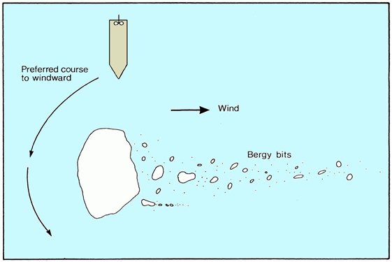
Figure 59 - Navigating around an iceberg and bergy bits (Courtesy of Capt. George Q. Parnell “Ice Seamanship”)
Text version: Navigating around an iceberg and bergy bits
Depiction of how a vessel should divert upwind from an iceberg as to avoid potential smaller bergy bits more easily affected by the wind, thus likely located downwind of the iceberg.
4.9.4.2 Growler detection
Growlers, because of their low freeboard and smooth relief, are the most difficult form of glacial ice to detect (both visually and on radar) and, therefore, are the most hazardous form of ice. Very little of a growler appears above the water surface because of the low freeboard of the ice and waves may completely cover it. Unless recently calved, water erosion will have made the surface of a growler very smooth, making it a poor radar target. In open or bergy water with good weather conditions visual detection of growlers is possible at 2 or 3 nautical miles from the vessel. In rough weather and heavy swells, a growler may remain submerged through the passage of 2 or more swells passing over it, making detection by any method even more difficult. Detection (on radar or visually) can be as little as 0.5 nautical miles from the vessel, if at all. It is important to keep a constant check on radar settings, particularly the tuning control (on manually tuned radars), to ensure that the radar is operating at maximum efficiency. Varying the settings can be useful, but care must be taken to ensure that the radar is retuned after any adjustment. It sometimes helps to sight a growler visually then tune the radar for maximum return.
Warning: Growlers are almost impossible to detect by radar. They pose an immense threat to vessels. Constant visual and radar monitoring must be maintained in any area where growlers are expected.
For a growler in an ice cover, it may be possible to detect it visually in clear conditions (because it is often transparent, green, or dark in appearance), but it is often not possible to discriminate it from surrounding ice clutter on marine radar. As the exact location of each growler cannot be identified for certain amongst ice floes, care must be taken to determine a safe speed through the ice-covered area when navigating by radar.
4.9.5 Old ice floes
Detection of old ice floes is primarily visual, because differentiation between first-year and old ice on marine radar is not possible. Travel through old ice can be reduced by using ice analysis charts to avoid areas of high concentrations of old-ice. However, mariners must watch for old ice even in areas where it is not identified on ice charts. Visual identification is possible up to 1 to 2 nautical miles from the vessel in good weather. Old ice can be distinguished from first-year ice by more rounded and weathered surface, light blue colour, higher freeboard, and a well-defined system of melt-water channels. Old ice is widely encountered in the Canadian Arctic, Baffin Bay, Davis and Hudson Straits, as well as the Foxe Basin, and is occasionally found in the Labrador Sea, off the north east coast of Newfoundland and on the Grand Banks. It is not a hazard in Cabot Strait, Gulf of St. Lawrence, Great Lakes, or the St. Lawrence River.
4.9.6 Visibility
Operating in restricted visibility is inevitable in, or near, ice-covered waters, either because of precipitation, fog or darkness. Travel through ice may, however, continue at night or in fog, which is common in the Arctic during the open water period, and visibility is often reduced by blowing snow in the Gulf of St. Lawrence during the winter.
All possible effort must be made to minimize the chances of collision with ice in poor visibility and the requirements of the regulation for preventing collisions at sea also apply. These efforts should include:
- maintenance of a constant visual and radar lookout
- use of searchlights at night (which may be counter-productive in fog or precipitation through reflected glare)
- reduction of speed before entering any ice field in poor visibility and not increasing speed before the threat has been determined
- reduction of speed in any ice situation where the ratio of glacial and old ice to first-year ice indicates a significant increase in the chance of collision with hazardous ice
- location of icebergs, bergy bits, and growlers on marine radar before they are obscured by sea or ice clutter, and tracking of these targets on Automatic Radar Plotting Aid (ARPA)
- switching between ranges to optimize the radar for iceberg detection when navigating in pack ice
- use of radar to detect icebergs and bergy bits by observing their radar shadows in mixed ice cover, and
- recognition of the difficulty of detecting glacial and old ice in open pack ice with marine radar when little or no radar shadow is recognizable
Many escorts occur in fog, when the escorted vessel must follow the icebreaker and maintain the required distance by radar. If the icebreaker suddenly slows or its position is lost on the radar screen, a collision may occur. It is important in these situations to maintain VHF radio contact and constant monitoring of the radar distance between vessels.
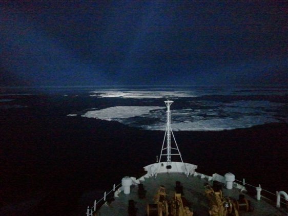
Figure 60 - The use of searchlights when transiting ice at night is essential (CCG)
4.10 Passage planning
The purpose of this section is to provide guidance in the procedures to be followed in the acquisition and use of information for planning passages in or near ice. Nothing in the instructions given here, or the processes that follow, either supersedes the authority of the mariner or relieves the officer of the watch from their normal responsibilities and from following the principles of good seamanship.
Passage planning for routes in ice-covered waters is based on standard navigational principles for passage planning (International Maritime Organization Resolution A. 893(21) adopted on 25 November 1999, Guidelines For Voyage Planning). The presence of sea ice along the planned route adds importance to the traditional practice of passage planning, necessitating the continual review of the entire process throughout the voyage. Passenger ships can also follow the Guidelines on Voyage Planning for Passenger Ships Operating in Remote Areas available on IMO A 2007-09.
Passage planning takes place in 2 phases:
- Strategic - when in port or in open water
- Tactical - when near or in ice-covered waters
Both strategic and tactical planning involve 4 stages:
- appraisal
- planning
- execution
- monitoring
The strategic phase may be considered small-scale (large area) and the assumption is that the vessel would be outside ice-covered waters, and days or weeks from encountering ice. The strategic phase may be revised several times before the tactical phase is commenced. The tactical phase may be considered large scale (small area) and is constantly being revised as the voyage unfolds.
Passage planning for open water is a fixed process in which most, if not all, the information is gathered before the vessel leaves the dock. The localised nature of some of the information for Arctic passage planning in ice means that information may become available only as the vessel moves into Canadian waters. The amount and extent of information is a function of the voyage type, so the more difficult voyages, such as early or late season, are supported with more resources, such as icebreakers, more frequent reporting of current ice conditions, and the appropriate ice forecasts. Passage planning in ice-covered waters, especially in the Arctic, is an evolving process that demands a flexible approach to the planning and execution.
Bridge manning
It is recommended that, because of the hazards of navigating in ice-covered waters, lookouts should be increased when in or near an area of ice. Navigation in ice can be very strenuous and Mariners should be careful not to overextend themselves, even if it means doubling the Officers of the Watch on the bridge or stopping the vessel at night to receive adequate rest. This applies not only for those on the bridge, but for engine-room staff who may be called upon for long periods of manoeuvring, clearing suctions, etc.
4.10.1 Strategic phase
4.10.1.1 Appraisal stage
This procedure involves the use of all information sources used in open water passage planning, plus any others that can be obtained to give the most complete picture of the ice conditions possible. Check to determine the availability of CIS ice information from CCG MCTS, CIS, CCG MARINFO Icebreaking and Web Cameras and from the Internet web sites where ice information is freely available.
4.10.1.2 Planning stage
Strategic planning is a forward-looking exercise to assess the ice conditions that the vessel is likely to encounter along the length of its planned route. Strategic planning relies on weather forecasts and available publications on the ice climatology of the region to be encountered in addition to standard nautical publications. This exercise may be planned over a period of hours, days, or even months depending on the route, destination and the nature of the ice environment to be encountered.
Note: For vessels that are not ice-strengthened and will be following ice instructions from the CCG Ice Operations Centre, the work at this point is the same as for a conventional voyage.
The Mariner will develop a route to the destination based on the information obtained in the appraisal stage, and have this laid off on the appropriate charts. The principles involved will be the same as in open water passage planning. The plan should be developed with the following limitations of the elements of the Ice Navigation system in mind:
- availability of ice information
- diminished effectiveness of visual detection of ice hazards in late season or winter voyages
- increased difficulty of detecting ice hazards in combined conditions of open ice and reduced visibility
Additional information to be marked on the chart could include:
- the anticipated ice edge, areas of close pack ice and the fast ice edge
- any areas of open water where significant pack ice may be expected, such as east Greenland ice in the vicinity of southern Greenland
- safe clearance off areas known to have significant concentrations of icebergs, such as off Cape Farvel and Disko Island in Greenland
- any environmentally sensitive areas where there are limitations as to course, speed, or on-ice activities. For example, ice fishing in St. Lawrence and Saguenay Rivers or traditional Inuit winter ice roads in the Arctic
4.10.1.3 Execution stage
Once the planning of the passage has been completed, the tactics for its execution can be decided upon. The estimated time of arrival for the destination can be developed based on the ice conditions expected along the route. Take into account any expected reductions in speed or large deviations in course for reduced visibility, passages in consolidated ice, areas of higher concentrations of old ice, and delays in waiting for information. The point at which it is considered necessary to ballast down to ice draft and to reduce speed should also be considered.
Consider when extra lookouts will be required or when watches are likely to be doubled for entering ice or approaching areas of low visibility or high numbers of icebergs / bergy bits / growlers.
4.10.1.4 Monitoring stage
Monitoring of the route should continue until the ice-covered areas are reached. As the vessel approaches ice-covered waters, the quality and quantity of ice information improves (with CIS ice analyses and forecasts), which increases the accuracy of estimates for times of arrival and may perhaps indicate a change in route.
The strategic evaluation may be redone, once or several times, on approach to the ice, depending on the amount of new information received.
Note: All vessels should monitor the updated routing instructions from the CCG Ice Operations centres.
4.10.2 Tactical phase
If no detailed ice information is available before reaching the ice-covered area, the vessel may be limited to the strategically planned route rather than a tactical one. All efforts should be made to obtain detailed information on ice conditions, particularly when consolidated ice is likely to be encountered, where high concentrations of old ice are expected or in highly mobile ice.
4.10.2.1 Appraisal stage
The gathering of tactical information is based mainly (but not exclusively) on the acquisition of CIS ice observation and analysis charts. The reception of these charts depends on the vessel being fitted with a facsimile machine capable of being tuned to the required frequencies. Additional inputs consist of marine radar (X and S-bands), visual observations, and processed radar imagery. Ice charts can be downloaded from the CIS web site on the Internet where satellite telephone contact is available. Helicopter (visual) reconnaissance can also be valuable where available.
4.10.2.2 Planning stage
Planning may be as for open water on large-scale charts, but also, if further information has been obtained, this may involve a track planned on a small-scale chart. Planning with additional information entails laying off the route to take the best advantage of optimum ice conditions, including:
- finding open water leads
- finding first-year ice leads in close ice or old ice fields
- avoiding areas of ridging
- avoiding areas of pressure or potential pressure
Once the track has been laid out, it has to be transferred to large-scale charts and checked for adequate water depth. The 2 sources have to be reconciled so that the best route is also a safe route. Once the route has been laid out it may indicate the need for further information.
4.10.2.3 Execution stage
Once the route has been determined, estimated times of arrival can be revised. Any change in weather conditions, particularly visibility or wind direction and speed, should be considered before executing the plan, as they are important for estimating pressure areas or where open water leads may be located.
4.10.2.4 Monitoring stage
Progress should be monitored on the chart by conventional means and ice navigation can continue.
4.11 High latitude navigation
Navigating in high latitudes requires great care in the procedures and in the use of information. The remoteness of the Arctic and the proximity to the North Magnetic Pole has an effect on the charts that are supplied and the navigation instruments that are used with them. This section discusses some of the effects and limitations on charts and instruments used in the Arctic.
4.11.1 Navigational appliances
The equipment requirements for vessels navigating north of 60° North latitude in Canadian waters in a shipping safety control zone, are contained in the Navigation Safety Regulations, 2020. In brief the following are required:
- 2 radars
- 2 Gyro compasses
- 2 echo sounders, each with an independent transducer
- 2 searchlights with 2 spare lamps;
- a weather facsimile receiver
- a spare antenna
4.11.2 Canadian Hydrographic Service navigational charts and publications
With respect to the Arctic, due to a lack of modern hydrographic surveys, the quality of charts, including paper charts, electronic navigational charts (ENC) and Raster Navigational Charts (RNC) can be poor. Many charts contain areas that are inadequately surveyed, or are based on old surveys where only spot soundings were collected, or where data was collected only along a single track. Mariners must be aware of these limitations.
There are 2 areas of concern regarding the use of charts in the Arctic. These are consideration of the different projections used versus southern waters and the accuracy of the surveys. While up-to-date charts and nautical publications are always critical to safe navigation, the Arctic requires a special understanding and the mariner should use all sources of updates, including Notices to Mariners and broadcast NAVWARN, to be sure paper charts, electronic charts and nautical publications are up to date. The CHS provides a monthly on-line updating service for ENCs and RNCs.
4.11.2.1 Projections
To compensate for the fact that the meridians converge as they near the pole the scale of the parallels is gradually distorted. In the Arctic, Mercator projections suffer too much distortion in latitude to be used for anything but large scale charts. As the latitude increases, the use of rhumb lines for visual bearings becomes awkward, as it is necessary to add ever-larger convergence corrections.
In the Arctic, the common projections are Lambert Conformal Conic, Polyconic, and Polar Stereographic. Polar Stereographic is popular as it provides minimum distortion over relatively large areas. Roughly 30%of CHS paper navigational charts in the north use one of these projections. The number of different projections makes it important, when changing charts, to check the type of projection and any cautions concerning distances, bearings, etc. For example, the habit developed with Mercator charts is to use the latitude scale for distance, which is not possible on Polyconic charts. Particular care must also be taken when laying off bearings in high latitudes, as a convergence correction may be needed even for visual bearings. To eliminate the corrections required by the use of compass bearings for fixing positions, three radar ranges of known features can provide an accurate position.
Warning: In the arctic, as in any other area, check the chart projection before use. Be aware of different projections within the same chart.
4.11.2.2 Accuracy
The accuracy of charts in the Arctic can vary widely according to the date of survey and the survey technologies available at that time. The more frequently travelled areas, such as Lancaster Sound, Barrow Strait, and the approaches to Nanisivik, are reasonably well surveyed, but many charts are based on aerial photography (controlled by ground triangulation) combined with lines of reconnaissance soundings or spot soundings gathered as helicopters land at many discrete locations. As of March 2021, the combined modern and adequate bathymetric coverage within Canada’s Arctic NORDREG Area is 15% while the same coverage in the Primary and Secondary Low-Impact Shipping Corridors is 40%. The CHS has acquired continuous bottom profiles and has recorded survey vessel positions using modern radio- or satellite-positioning systems, and meet present-day international hydrographic standards for surveying, including having conducted detailed examinations where the data indicated possible shoaling of the bottom. In general, the more recent the survey, the more reliable and accurate the results. The very latest surveys frequently, but not always, consist of 100% bottom insonification using multi-beam sonar, sweep multi-transducer systems, and airborne laser bathymetry systems.
Even new editions of charts may contain a mix of older and newer data. The appearance of depth contour lines on new charts does not necessarily indicate any new information.
Precautions to be taken when using navigational charts for Arctic areas include:
- checking the projection and understanding its limitations
- checking the date of the hydrographic survey and reviewing the Source Classification Diagram
- using range and bearing to transfer positions from chart to chart
- checking for evidence of reconnaissance soundings
- using the largest scale chart available
- checking for the method of measuring distances and taking bearings
- updating charts and nautical publications by checking for Notices to Mariners, NAVWARN and any other sources for chart corrections.
It is important to note that raster charts are electronic copies of the paper charts, and there is normally no increase in accuracy simply because a charts is digital. Most S-57 ENCs and BSB RNCs are based on the paper chart; however, in the Arctic there are some S-57 ENCs that do not have a paper chart equivalent and may be based on modern surveys. It is important to examine the meta-data in the electronic chart display to assess this information. For more details and the latest information on the status of Arctic charts please visit the CHS Website.
4.11.3 Chart horizontal datum
One of the principal problems with charts in the Arctic concerns the horizontal datum on which the chart is based. With more and more vessels using accurate positioning systems such as the global positioning system (GPS) or the Russian global navigation satellite system (GLONASS), the greater the problem will become. Regarding GPS, the positions are referenced to the World Geodetic System (WGS) which is virtually equivalent to the North American Datum (NAD). If navigating on a NAD paper chart with GPS there would be no corrections to apply. If plotting on a NAD paper chart the appropriate corrections must be manually applied. Digital charts (raster or vector) issued by the Canadian Hydrographic Service are always on NAD.
Mariners should always cross-reference positions plotted on electronic charts with the largest possible scale paper charts of the same area, as different electronic chart systems available on the market may vary greatly in the information presented on the electronic display. There can be instances where the vessel is plotted on a paper chart as being afloat in deep water, and yet is shown to be ashore on an electronic display. Conversely, a GPS position, when plotted by latitude and longitude on a paper chart, may indicate that the vessel is on the shore when 3 radar ranges from the shoreline indicate that the vessel is safely afloat.
Note: The value of a chart depends to a great extent on the accuracy and detail of the surveys on which it was based.
Mariners should proceed with due caution and prudent seamanship when navigating in the Arctic especially in poorly charted areas or when planning voyages along new routes. Additional information may be found in the Notices to Mariners, NAVWARN, Notices to Mariners Annual Edition as well as Sailing Directions.
4.11.4 Compasses
The magnetic compass can be erratic in the Arctic and is frequently of little use for navigation.
Note: The magnetic compass depends on its directive force upon the horizontal component of the magnetic field of the earth. As the north magnetic pole is approached in the Arctic, the horizontal component becomes progressively weaker until at some point the magnetic compass becomes useless as a direction measuring device.
If the compass must be used the error should be checked frequently by celestial observation and, as the rate of change of variation increases as the pole is approached, reference must be made to the variation curve or rose on the chart. In high latitudes, generally above 70°N in the Canadian Arctic, the magnetic compass will not settle unless the vessel remains on the same heading for a prolonged period, so it can be considered almost useless anywhere north of Lancaster Sound.
The gyro compass is as reliable in the Arctic as it is in more southerly latitudes, to a latitude of about 70°N. For navigation north of 70°N special care must be taken in checking its accuracy. Even with the compensation given by the latitude corrector on certain makes of compass, the gyro continues to lose horizontal force until, north of about 85°N, it becomes unusable. The manual for the gyro compass should be consulted before entering higher latitudes. The numerous alterations in course and speed and collisions with ice can have an adverse effect on its accuracy. Therefore, when navigating in the Arctic:
- the ship's position should be cross-checked with other navigation systems, such as electronic position fixing devices, where course history could be compared with course steered (allowing for wind and current)
- the gyro error should be checked whenever atmospheric conditions allow, by azimuth or amplitude
- in very high latitudes approaching the North Pole, the most accurate alternative to the gyro compass for steering is the GPS, which, if working as it should, can also be used as a check on “course-made-good” over the ground
4.11.5 Soundings
When in areas of old or sparse hydrographic survey data, the echo sounder should be run so as to record any rocks or shoals previously undetected, although it is doubtful that the sounder would give sufficient warning to prevent the vessel going aground. Even in areas of the high Arctic that are well surveyed, the echo-sounder should be run, as vessel traffic in the area is sparse and many of the routes will not have been sailed previously by deep-draft vessels.
Many of the navigational charts in the Arctic consist largely of reconnaissance soundings (not done as part of a survey). As a result, it is not likely that a line of soundings would be of much use in finding a position. Additionally, false echoes may be given by ice passing underneath the echo sounder or by the wash when backing or ramming in ice. In heavy concentrations of ice cover, the echo sounder may record multiple returns so that it is impossible to distinguish which one represents the actual depth beneath the keel. When soundings are lost in this manner, it may help to stop the vessel in the ice until a stable echo can be discerned amongst the random spurious echoes.
4.11.6 Position fixing
Problems encountered with position fixing arise from either mistaken identification of shore features or inaccurate surveys. Low relief in some parts of the Arctic makes it hard to identify landmarks or points of land. Additionally, ice piled up on the shore or fast ice may obscure the coastline. For this reason radar bearings or ranges should be treated with more caution than measurements in southern waters. Visual observations are always preferable. Sometimes it is possible to fix the position of grounded icebergs and then to use the iceberg for positioning further along the track, if performed with caution.
Large areas of the Arctic have not yet been surveyed to the same standards as areas further south, and even some of the more recently produced charts are based on reconnaissance data. To decrease the possibility of errors, 3 lines (range, or less preferably bearings) should always be used for positions. Fixes using both sides of a channel or lines from 2 different survey areas should be avoided. Because of potential problems, fixes in the Arctic should always be compared with other information sources, such as electronic positioning systems. Reliance on one information source should be avoided.
4.11.7 Use of radar for navigation in arctic waters
In general, Arctic or cold conditions do not affect the performance of radar systems. Occasionally weather conditions may cause ducting, which is the bending of the radar beam because of a decline in moisture content in the atmosphere. This effect may shorten or lengthen target detection ranges, depending on the severity and direction of the bending. A real problem with radar in the Arctic concerns interpretation of the screen for purposes of position fixing.
The Automatic Identification System (AIS) has now become mandatory for most large vessels likely to be encountered in Canadian waters and is a useful tool to separate echoes of vessels from icebergs on a radar display. It is also very useful to be able to identify a nearby but unseen vessel when working in ice, for the trading of ice information, details of progress and so on by voice radio or satellite communication (e-mail).
Fixing solely by a radar range and bearing, from a point of land or by the use of radar or gyro bearings, is not recommended. Fixing by 2 or more radar ranges is the best method in Arctic waters, but care is required in the correct selection and identification of prominent features on the radar screen. The following difficulties, peculiar to radar fixing in the Arctic, may be encountered:
- Difficulty in determining where the ice ends and the shore-line begins. A reduction in receiver gain should reduce the ice return.
- Disagreement between ranges, caused by ranging errors or chart inaccuracies. The navigator should attempt to range on the nearest land and should not range on both sides of a channel or long inlet.
- Uncertainty as to the height and, therefore, the detection range of land masses because of a lack of topographical information on the chart.
- Lack of fixing aids in the area and sparse, dated or non-existent hydrographic surveys.
4.11.8 Global positioning system
The GPS, is a space-based radio-navigation system that permits users with suitable receivers, on land, sea or in the air, to establish their position, speed and time at any time of the day or night, in any weather conditions.
The navigational system consists nominally of 32 operational satellites in 6 orbital planes, and an orbital radius of 26,560 kilometres (about 10,900 nautical miles above the earth). Of the 32 satellites, 31 are considered fully operable and the remaining three although functioning, deemed “spares”. The orbital planes are inclined at 55° to the plane of the equator and the orbital period is approximately 12 hours. This satellite constellation allows a receiver on earth to receive multiple signals from a number of satellites 24 hours a day. The satellites continuously transmit ranging signals, position and time data that is received and processed by GPS receivers to determine the user’s three-dimensional position (latitude, longitude, and altitude), velocity and time.
Although the satellites orbit the earth in a 55° plane, the positional accuracy all over the globe is generally considered consistent at the 100-metre level. For a vessel at a position 55° north or south latitude or closer to the pole, the satellites would be in a constellation around the vessel with the receiver actually calculating the ship’s Horizontal Dilution of Precision (HDOP) with satellites possibly on the other side of the pole. With a vessel at or near the North Pole all the satellites would be to the south, but well distributed in azimuth creating a strong fix. The exception to this is the vertical component of a position which will grow weaker the further north a vessels sails because above 55°N there will not be satellites orbiting directly overhead.
There are a variety of sources of error which can introduce inaccuracies into GPS fixes especially in polar regions such as tropospheric delays and ionospheric refraction in the auroral zone. The troposphere varies in thickness from less than nine kilometers over the poles to over 16 kilometres on the equator which can contribute to propagation delays due to the signals being refracted be electromagnetic signal propagation. This error is minimized by accurate models and calculations performed within the GPS receiver itself. The ionospheric refraction in the auroral zone (the same belt in which the aurora borealis / aurora australis phenomena occur) caused by solar and geomagnetic storms will cause some error.
One minor advantage of the drier, polar environment is the efficiency of the receiver to process satellite data. In warmer, marine climatic conditions it is more difficult to model a wet atmosphere.
If the datum used by the GPS receiver in calculating latitude and longitude is different from the horizontal datum of the chart in use, errors will occur when GPS derived positions are plotted on the chart. GPS receivers can be programmed to output latitude and longitude based on a variety of stored datum sets.
Since 1986 the CHS has been converting CHS charts to NAD83. Electronic charts are typically on NAD83 however it is important to check the electronic chart meta-data to be certain. Information on the chart will describe the horizontal datum used for that chart and for those not referenced to NAD83, corrections will be given to convert NAD83 positions to the datum of the chart. The title block of the chart will describe the horizontal datum used for the chart and will give the corrections to convert from the datum of the chart to NAD83 and vice versa. A note of caution regarding raster charts: the title block, since it is an image taken from the paper chart, may indicate the chart is not on NAD83 however the Canadian Hydrographic Service issues all its raster charts on NAD83 therefore no correction is necessary.
Global navigation satellite system
The GLONASS is a radio-based satellite navigation system operated for the Russian government by the Russian Aerospace Defence Forces. It complements and provides an alternative to the United States GPS and is currently the only alternative navigational system in operation with global coverage and the same precision. The GLONASS constellation has 24 operational satellites to provide continuous navigation services worldwide, with 7 additional satellites for spares and maintenance.
4.11.10 Radios
Radio communications in the Arctic, other than line of sight, are subject to interference from ionospheric disturbances. Whenever communications are established alternative frequencies should be agreed upon before the signal degrades. Use of multiple frequencies and relays through other stations are the only methods of avoiding such interference.
4.11.11 INMARSAT
The International Mobile Satellite Organization (IMSO) owns and operates 3 global constellations of the Inmarsat 14 satellites flying in geosynchronous orbit 37,786 km (22,240 statute miles) above the Earth. Use of INMARSAT services in the Arctic is the same as in the south, until the vessel approaches the edge of the satellite reception at approximately 82°N. At high latitudes where the altitude of the satellite is only a few degrees above the horizon, signal strength is dependent on the height of the receiving dish and the surrounding land.
As the vessel leaves the satellite area of coverage the strength of the link with the satellite will become variable, gradually decline, and then become unusable. When the strength has diminished below that useable for voice communications, it may still be possible to send telexes. Upon the ship's return to the satellite area of coverage there may be problems in obtaining the satellite signal and keeping it until the elevation is well above the horizon.
4.11.12 Mobile Satellite (MSAT) / SkyTerra communications satellite system
MSAT-1 and MSAT-2 geostationary satellites have been delivering mobile satellite voice and data services to North America since 1995. The latest satellite, SkyTerra-1, was launched in orbit on November 14, 2010. The satellite phone network and local cellular networks are compatible, allowing a user to communicate over the regular cellular network, and only rely on the satellites in areas outside the range of cell phone towers. This is useful in sparsely populated areas where the construction of cell towers is not cost-effective, as well as to emergency-response services which must remain operational even when the local cellular network is out of service.
4.11.13 Iridium satellite system
The Iridium satellite constellation consists of 66 cross-linked low Earth orbit (LEO) satellites, plus spares, that orbit from pole to pole with an orbit of roughly 100 minutes. This design means that there is excellent satellite visibility and service coverage at the North and South poles.
4.12 Search and Rescue
The Canadian Armed Forces are responsible for coordinating search and rescue activities in Canada, including Arctic waters, and for providing dedicated SAR aircraft to aid in marine SAR incidents. A SAR service is defined as the performance of distress monitoring, communication, coordination, and SAR activities through the use of public and private resources. Any incident requiring assistance must be reported to an MCTS centre.
The CCG works with the Canadian Armed Forces to coordinate marine SAR activities within the Arctic. They search for and provide assistance to people, vessels, and other craft that are, or are believed to be, in imminent danger. They provide dedicated marine SAR vessels in strategic locations. There are no dedicated marine SAR units deployed in the Arctic waters on a year-round basis, however, CCG units deployed in the Arctic during the navigation season are designated for SAR activities as their secondary role. SAR aircraft are staged into the Arctic from more southerly bases in the event of a SAR incident, or may already be present on training missions.
Joint rescue coordination centres, covering all waters under Canadian jurisdiction, are staffed 24 hours a day by Canadian Armed Forces and CCG personnel. They are located in Victoria, British Columbia, Trenton, Ontario and Halifax, Nova Scotia. The joint rescue coordination centre (JRCC) in Trenton provides emergency response and alerting systems for SAR in the Great Lakes and Arctic regions.
Additional information on SAR services in Canadian waters can be found in the following publication, available from CCG:
4.13 Reporting oil spills
Any incident involving the spillage of oil or petroleum lubricating products into the marine environment must be reported immediately to NORDREG CANADA. In addition, the operator should report the incident to the 24-hour Spill Report Centre.
Nunavut and Northwest Territories (Yellowknife): (867) 920-8130
Yukon (Whitehorse): (867) 667-7244
Canadian Coast Guard (Quebec City / Iqaluit) - Toll free: 1-800-265-0237 (24 hours)
For more information consult ECCC Environmental emergency regulations: reporting a spill or release.
4.14 Fuel and water
The ASSPPR requires all vessels operating in the NORDREG Zones to have sufficient fuel and water on board to complete their intended voyages and to leave all Zones. A vessel’s capability of making its own fresh water will be taken into account in this regard. There are no refuelling or watering facilities in the Arctic unless the cruise operator makes special arrangements during the planning phase. Transport Canada will require an estimate of fuel consumption anticipated for the full voyage and NORDREG CANADA will need to be informed of the volume of fuel on board prior to the vessel entering the first Zone.
4.15 Environmental disturbances on ice transportation, birds, animals and fish
Environmental effects of a harmful nature are becoming an increasingly important concern in marine navigation. This concern applies to navigation in ice-covered waters where special navigational considerations may have a potential for environmental disturbance. While it is clear that accidents can have a detrimental effect on the environment, even normal marine operations have the potential to affect valued components of the environment. Valued components may include the following:
- rare or threatened species or habitats
- species or habitats which are unique to a given area
- species or habitats which are of value for aesthetic reasons
- species which may be used by local populations
- cultural and socio-economic practices of local populations
There are numerous potential effects that are not unique to ice environments; however, the presence of ice, cold temperature, and remote location, may enhance the level of disturbances over similar activities in milder environments.
Some specific environmental disturbances which are unique to ice-covered waters include the possible restriction of on-ice travel of local populations when a track is created in the ice, potential disruption of the formation or break-up process for local ice edges and, in the early spring, disruption of seal breeding on the ice.
Potential disturbances arising from normal operations are generally location specific. In most cases, avoiding sensitive areas and times of the year will mean that disturbances can be avoided. Adherence to navigation practises, as outlined in this manual, will minimize the risk of environmental disturbances from navigation in ice. Mariners should consider how their vessel might affect the environment and take measures to minimize the disturbance.
4.16 Ice information
To conduct a sea voyage safely and efficiently, a mariner must have a well-founded understanding of the operating environment. This is especially true for navigation in ice. It is the responsibility of all mariners to ensure that before entering ice-covered waters, adequate ice information is available to support the voyage from beginning to end.
The ways and means of acquiring ice information suitable for navigation vary from one source to another. Content and presentation formats also vary depending on the nature of the system used to acquire the raw data, and the degree of analysis or other form of enhancement which may be employed in generating the final product.
Many information sources are not normally or routinely available at sea, especially outside Canadian waters. In some cases prior arrangements may be necessary to receive particular products. The mariner is encouraged to consider carefully the required level of information, and to make appropriate arrangements for its delivery to the vessel.
4.16.1 Levels of ice information
It is possible to distinguish 4 levels of ice information, characterised by increasing detail and immediacy:
- background
- synoptic (summary or general survey)
- route specific
- close range
Background information is primarily historical in nature. It describes the natural variability in space and time of ice conditions for the region of intended operation. It may also describe the relationship of ice conditions to other climatological factors including winds, currents, and tides. It is applied very early in the strategic planning process, but it may also be useful at any time during the voyage.
At the synoptic level, ice conditions are defined for specific regions and time periods. The information may provide either current or forecast ice conditions but, in either case, it is not very detailed. As synoptic information is normally used days or even weeks before entering the ice, and because conditions are often dynamic, its greatest value is as a support tool for strategic planning.
Route-specific information provides a greater level of detail than synoptic information, usually for smaller areas. The detail provided may extend to the identification of individual floes and other features of the ice cover, and is most useful at the tactical planning stage.
Close-range information identifies the presence of individual hazards which lie within the immediate path of the ship. This level of information provides critical support during monitoring and execution of the tactical passage plan.
CIS, provides ice information and long-range forecasts to support marine activities. At the synoptic level, the Ice Operations Division of the CIS provides valuable strategic planning information through a series of plain language bulletins, warnings, and short-range forecasts for ice and iceberg conditions. These are broadcast live by marine radio, with a range of up to 320 kilometres. Broadcast frequencies and schedules are listed in the CCG publication RAMN, issued seasonally. Taped bulletins are broadcast continuously from CCG radio stations with an effective range of 60-80 kilometres. Alternatively, most of this information is available on the CIS website.
Extended forecasts (including seasonal outlooks and twice-monthly 30-day forecasts), and daily ice analysis charts, are available through the web, email, mail or facsimile subscription. For further information contact:
Website:
Latest ice conditions - Canada.ca
Address:
Canadian Ice Service
719 Heron Road, Annex E
Sir Leonard Tilley
Ottawa, Ontario
K1A 0H3
- Email: ec.cisclients-scgclients.ec@canada.ca
- Telephone: 1-877-789-7733
The most important external source of information available to the vessel is the broadcast of ice analysis charts by the CIS. For vessels equipped with their own reconnaissance helicopter, aerial visual observations may provide considerably more ice information at the route planning and tactical levels.
4.16.2 Remote sensing systems
With special purpose receiving and processing equipment, vessels may take advantage of airborne and satellite borne remote sensing systems for complementary synoptic level ice information.
The CIS no longer use airborne imaging radar systems for ice reconnaissance, which were able to transmit raw data directly to the CCG Ice Operations centres.
Many commercially available systems enable vessels to receive direct transmission of weather satellite imagery which may be used to assess regional ice distribution. These systems are designed to receive the VHF (137 MHz) image transmission from various weather satellites via inexpensive personal computer software. Image resolution is in the range of 3 to 4 kilometres, providing suitable information for synoptic level voyage planning. The low cost of these systems (typically in the tens of thousands of dollars) makes them suitable for a larger number of vessels transiting ice-covered waters (figure 61).
Canada has a fully operational imaging radar satellite known as RADARSAT-2, which provides high-resolution (100 metre) global coverage of ice-covered waters on a nearly continuous basis. RADARSAT-2 has the capability to send and receive data in both horizontal (H) and vertical (V) polarizations. Images acquired with the various combinations of polarizations on transmit and receive can be displayed on single channels or in various combinations including ratios and false colour composites.
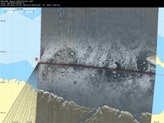
Figure 61 - Aerial ice reconnaissance image displayed in a GIS system (Courtesy of CIS)

Figure 62 - RADARSAT-2 HH image of M’Clure Strait (MDA 2009)
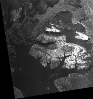
Figure 63 - RADARSAT-2 HV image of M’Clure Strait (MDA 2009)
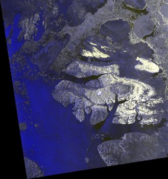
Figure 64 - RADARSAT-2 RGB221 image of M’Clure Strait (MDA 2009)
Figures 62 to 64 are RADARSAT-2 images that were taken on September 14, 2008 in M’Clure Strait.
Figure 62 is an HH polarization (horizontal send and horizontal receive). In the image, it is difficult to differentiate the multi-year ice from other ice types.
Cross-polarization modes combine horizontal send with vertical receive (HV) or vice versa (VH). In the HV image (figure 63) the multi-year ice clearly stands out but the thinner ice types are not as evident.
A combination of HH, HV and the colours red, green and blue (RGB) can help to differentiate all the ice types in satellite images.
Figure 64 is an RGB221 image with very good detection of multi-year ice, with an increased detection of strips of thinner ice when compared to the previous images.
4.16.3 Canadian Ice Service ice charts
Ice charts issued by the CIS use standard World Meteorological Organization terms and symbols to describe ice conditions at different locations. The mariner should be aware that these charts are synoptic level information sources, and the ice conditions depicted are averages for the area. There is always the possibility that local ice conditions may differ significantly from those depicted on the chart. Maintaining manoeuvrability for the avoidance of locally heavy ice conditions is an important consideration when using ice charts at the route planning level.
The ice analysis charts issued daily by CIS do not show areas of ridged ice, rubbled ice, or ice under pressure. They do, however, indicate the general drift in nautical miles per day of individual ice-fields, so that developing pressure can be deduced. In using this information, the mariner should consider at all times the potential for ice drift and changes in ice conditions, which is especially important where navigation corridors are constrained by shallow water, and where winds, currents, and/or tides may result in zones of ice convergence.
The ice analysis chart is the primary map product produced at the CIS. It is produced daily and valid at 1800 UTC during the operating season, and represents the best estimate of ice conditions at the time of issue. The chart is prepared in the afternoon so that it may be delivered to users in time for planning the next days' activities.
An example of how to read a daily ice analysis chart is presented in figure 65. The CIS uses codes and symbols to describe all ice forms, conditions, and concentrations as accepted by the World Meteorological Organization. The ice codes are depicted in oval form, known as the Egg Code, which is completely described in MANICE, and is outlined in this section. The use of codes and symbols varies according to the type of ice chart:
- current daily ice chart: area specific, most detailed
- regional weekly ice chart: smaller scale, less detailed
The basic data concerning concentrations, stages of development (age), and form (floe size) of ice are contained in a simple oval form. A maximum of three ice types are described within the oval. This oval, and the coding within it, are referred to as the “Egg Code”.
The Egg Codes symbols in the code are classed into four categories of ice information:
- Total concentration
- top level
- Ct - Total concentration of ice in the area, reported in tenths.
- Partial concentrations of ice types
- second level
- CaCbCcCd - Partial concentrations of thickest (Ca), second thickest (Cb), third thickest (Cc), and fourth thickest (Cd) ice, in tenths.
- Ice type corresponding to the partial concentrations on the second level
- third level
- Stage of development of the thickest (So), second thickest (Sa), third thickest (Sb), and fourth thickest (Sc) ice, and the thinner ice types (Sd and Se), of which the concentrations are reported by Ca, Cb, Cc, and Cd, respectively.
- Predominant floe size category for the ice type and concentration
- bottom level
- Floe size corresponding to Sa, Sb, Sc, Sd, and Se (when Sd and Se are greater than a trace).
Tables 10, 11, and 12 list the codes used in the egg codes for sea ice and lake ice stages of formation and floe sizes, respectively.
Table 10 - Egg coding for sea ice stages of development (So Sa Sb Sc Sd Se)
| Description | Thickness | Code |
|---|---|---|
| New ice | <10 cm | 1 |
| Nilas; ice rind | 0-10 cm | 2 |
| Young ice | 10-30 cm | 3 |
| Grey ice | 10-15 cm | 4 |
| Grey-white ice | 15-30 cm | 5 |
| First-year ice | 30-200 cm | 6 |
| Thin first-year ice | 30-70 cm | 7 |
| Thin first-year ice first stage | 30-50 cm | 8 |
| Thin first-year ice second stage | 50-70 cm | 9 |
| Medium first-year ice | 70-120 cm | 1• |
| Thick first-year ice | 120-200 cm | 4• |
| Old ice | 7• | |
| Second-year ice | 8• | |
| Multi-year ice | 9• | |
| Ice of land origin | ▲• | |
| Undetermined or unknown | X |
Table 11 - Egg coding for lake ice stages of development
| Description | Thickness | Code |
|---|---|---|
| New lake ice | <5 cm | 1 |
| Thin lake ice | 5-15 cm | 4 |
| Medium lake ice | 15-30 cm | 5 |
| Thick lake ice | 30-70 cm | 7 |
| Very thick lake ice | >70 cm | 1• |
Table 12 - Egg coding for floe sizes (Fa Fb Fc Fd Fe Fp Fs)
| Description | Code |
|---|---|
| Pancake ice | 0 |
| Small ice cake; brash ice | 1 |
| Ice cake | 2 |
| Small floe | 3 |
| Medium floe | 4 |
| Big floe | 5 |
| Vast floe | 6 |
| Giant floe | 7 |
| Fast ice, growlers, or floebergs | 8 |
| Icebergs | 9 |
| Undetermined or unknown | X |
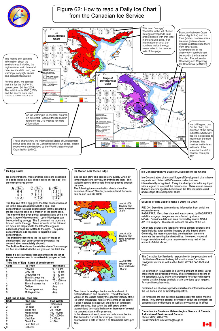
Figure 65 - How to read a daily Ice Chart from Canadian Ice Service
Text version: How to read a daily Ice Chart from Canadian Ice Service
The figure overlaps a Stage of Development chart and an Ice Concentration chart. It summarizes in bubbles the different details found on these products that were covered in the publication.
In the top left corner the Canadian Ice Service logo is depicted and in the bubbles we read for Stage of development Chart:
- (pointing to an egg code on the chart) This is an “ice-egg” with the letter to left corresponding to all areas labelled the same. Next page has information about the numbers found inside the egg.
- (pointing to the right corner legend for the drift vector arrow) Ice drift legend box. The arrows on the chart indicates the expected direction the ice will move in the next 24 hours. The inner number estimates the daily drift in nautical miles.
- (pointing at the waters more free of ice on both type of charts) Open Water with possible ice traces are shown in light-blue and Bergy Waters are shown with red triangles. White areas are ice free unless identified as “no forecast” like here.
- (pointing at main legends on both type of charts) These charts show the international Stage of Development and the Ice Concentration colour codes. These codes were standardized by the World Meteorological Organization (WMO).
- (pointing at the title legend of Ice Concentration chart) The Legend box contains information about the analysis area including the region name, valid time and date, source data used, ice warnings, copyright details and contact information. For this chart, we can see that it's for the Hudson Strait on 17-June-2021, valid time is 1800 (UTC) and the source data is RADARSAT…
- (pointing at the ice warning in effect box besides the title legend box) Ice Warning in effect for an area. Ice bulletin found on CIS website has more info.
The figure is split, following on the next page of the document.
Continuation of the figure are 6 bubble boxes that describe more recapitulation of info about these chart products.
-First Bubble-
Ice Egg Codes:
Ice concentrations, types and floe sizes are described in a code inside an oval shape called an "ice egg" like the ones pictured below.
(A, C, E eggs are in examples with their code numbers)
The top line of the egg gives the total concentration of ice in the area associated with the egg. The concentration is a ratio expressed in tenths describing the ice-covered area as a fraction of the entire area. The second line gives partial concentrations of the ice types (stage of development). Up to 5 ice types can be reported by an egg. The 3 dominant ice types are located inside the egg. Trace amounts of the thickest ice types are displayed to the left of the egg and additional groups are written to the right. The partial concentrations add together to equal the total concentration.
The third line describes the ice type or “stage of development” that corresponds to the partial ice concentration immediately above it.
The bottom line shows the relative size of the average ice floe associated with the ice types on the third line.
Note: If a dot is present, then all numbers to the left of the dot are understood to have the dot (.) as part of their code.
Third line of Egg - Stage of development:
- Code (1) - Ice Type (New ice) - Thickness (0-10cm)
- Code (4) - Ice Type (Grey ice) - Thickness (10-15cm)
- Code (5) - Ice Type (Greywhite ice) - Thickness (15-30cm)
- Code (7) - Ice Type (Thin first-year ice) - Thickness (30-70cm)
- Code (1.) - Ice Type (Medium first-year ice) - Thickness (70-120cm)
- Code (4.) - Ice Type (Thick first-year ice) - Thickness (more than 120cm)
- Code (7.) - Ice Type (Old ice) - Any thickness
- Code (8.) - Ice Type (second-year ice) - Any thickness
- Code (9.) - Ice Type (Multi-year ice) - Any thickness.
Last line of Egg - Floe size
- Code (1) - Floe Size (Brash) - Floe Width (less than 2 metres)
- Code (2) - Floe Size (Ice cake) - Floe Width (2-20m)
- Code (3) - Floe Size (Small floe) - Floe Width (20-100m)
- Code (4) - Floe Size (Medium floe) - Floe Width (100-500m)
- Code (5) - Floe Size (Big floe) - Floe Width (500-2000m)
- Code (6) - Floe Size (Vast floe) - Floe Width (2-10km)
- Code (7) - Floe Size (Giant floe) - Floe Width (more than 10km)
- Code (8) - Floe Size (Land fast ice)
- Code (9) - Floe Size (Icebergs)
-Second Bubble-
Ice Motion near the Ice Edge
Sea ice can grow and spread very quickly when air temperatures are very low and winds are light. This typically occurs after a cold front has passed through the area.
The following ice concentration charts show the evolution of ice off Gander, Newfoundland, between Jan 24 and Jan 26, 2008.
Small zoomed frames show parts of ice concentration charts with partial polygons with egg code letter without details.
- #1 Jan 24 2008 Daytime high temp at Gander -5.5C
- #2 Jan 25 2008 Daytime high temp at Gander -10.5C
- #3 Jan 26 2008 Daytime high temp at Gander -15.2C
Over these three days, the ice north and east of Botwood formed and thickened. The drift arrows visible on the charts display the general velocity of the ice within 10 nautical miles of the centre of the arrow. It does not take into account the effect of landmass within the area, thus when the drift arrow points towards land this could indicate an increase of coastal ice concentration and/or pressure.
In the absence of wind, water currents move the ice. The Labrador Current, for example, moves ice southward at a rate of about 5 to 10 nautical miles per day.
-Third Bubble-
Ice Concentration vs Stage of Development Ice Charts
Ice Concentration charts and Stage of Development charts have separate and distinct (WMO) colour codes that are internationally recognised. Every ice chart produced is equipped with a legend to interpret the colour code. There are no colours that are interchangeable between an Ice Concentration chart and a Stage of Development chart.
-Fourth Bubble-
Sources of data used to make a Daily Ice Chart
- RECON: Describes date and area information from aerial ice reconnaissance.
- RADARSAT: Describes date and area covered by RADARSAT satellite imagery. Images are not affected by clouds.
- NOAA: Describes date and area covered by source NOAA.
- AVHRR imagery. Clouds can obscure the view of the ice.
Other data sources are listed after these primary sources and could include: other satellite imagery or ship-based charts. Generally, the more source data the chart has, the more accurate the resulting ice chart will be. However, issues of image resolution and space requirements may restrict the amount of detail shown.
-Fifth Bubble-
The Canadian Ice Service is responsible for the production and distribution of ice and iceberg information over Canadian Navigable waters as well as the Arctic METAREAS XVII and XVIII.
Ice Information is available in a varying amount of detail. Large area charts are produced weekly as a climatological record of ice conditions. Daily charts are produced for areas with active marine activity. Image analysis charts are done upon request for specific requirements.
Dedicated ice observers provide valuable ice information about the ice from a ship or aircraft perspective.
Ice forecasts are text bulletins available daily for active marine areas. They provide general information about the dominant ice concentration and ice type as well as any warnings in effect.
-Sixth Bubble-
Canadian Ice Service - Meteorological Service of Canada
A division of Environment Canada
Phone: (877) 789-7733
Email: Weather.Info.Meteo@ec.gc.ca
4.16.3.1 Interpreting ice charts
Observed or interpreted ice charts require boundaries for all changes of ice parameters. However, the daily ice analysis chart requirements have been developed in co-ordination with the CCG. In particular, these requirements address the placement of mandatory boundaries through differing ice types, concentrations, and floe size which are of significance to navigation.
Table 13 - Concentration
-

<1/10 Open water
-

1-3/10 Very open drift
-

4-6/10 Open drift
-

7-8/10 Close pack/Drift
-

9/10 Very close pack
-

9+/10 Very close pack
-

10/10 Compact/Consolidated ice
A daily ice analysis chart will not normally show a boundary between ice conditions that vary by only one tenth, except when very close or compact conditions exist. Total concentration is the determining factor in defining ice boundaries, except that when first-year or thicker ice is present, any new ice which may also be present is ignored.
The ice edge is the boundary between open water and concentrations of 1 or more tenths of ice. This implies that traces of ice may be expected beyond the ice edge. When ice types are grey-white or thicker, an additional solid boundary between close drift/pack, 7 to 8 tenths, and very close drift/pack, 9 to 9+ tenths, is made at the discretion of the forecaster.
The user should be aware that ice types are considered to be level and undeformed. Due to rafting and ridging, there will usually be traces of thicker ice present. When present, second-year ice, code 8., and Multi-year ice, code 9., are used in the Arctic during the October to December period, and at other times when the situation is well known. A boundary is not required between these 2 ice types. Along the Labrador coast and in Newfoundland waters, old ice, code 7., is used.
Navigation through thicker ice types in larger floes is more difficult than in smaller floes. When first-year or thicker ice is present, with a concentration of 6 tenths or more, a boundary is required between areas with medium or larger floes, code 4 or greater, and areas with small floes, code 3 or less.
Strips and patches are often used on a chart in an attempt to describe ice conditions accurately when the total concentration in an area is in the very open to open drift category. In these areas, especially along ice edges, the ice is arranged by winds, currents, and tides into strips and patches of very close ice with large patches of open water in between. Similarly, the use of 2 egg codes joined by the strip symbol is often used to depict strips and patches of close or very close ice of a thicker type. In this case the patches are embedded in a broad area of thinner ice cover. A vessel which can make good progress in the average concentration of open pack ice should take care to reduce speed when encountering a strip or patch of the more heavily concentrated ice.
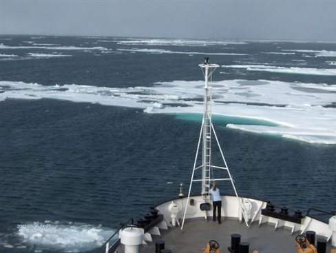
Figure 66 - Vessel encountering strips of multi-year ice (CCG)
The daily ice analysis chart is a static picture of ice conditions at 1800 UTC. Ice is generally in a state of mobility, depending on meteorological and oceanographic conditions. Drift arrows are included on the chart to assist the user in assessing the change in ice conditions over the next 24 hours. The arrows indicate the expected 24-hour net drift of freely moving ice, based on forecast winds and known currents. Wind-driven forces are directly proportional to the sail factor of the ice. The sail factor is directly proportional to the ice thickness and indirectly proportional to total concentration and floe size. This means that the fastest moving ice, such as very open drift, would be expected to drift at the indicated rate. There is a delay after the start of strong winds before an ice-field ice will start to drift downwind, and the ice-field will continue to drift in that direction for a period of time after the wind ceases, or changes direction.
The arrows can be used as an indication of ice pressure when placed in an area of thicker ice and directed toward even thicker ice or a coastline. Conversely, areas of easing pressure or development of leads would be indicated by an expected offshore drift.
The user should be aware that because of melt and destruction, an ice edge may not be advancing at the rate indicated. Conversely, with ice growth, the edge may be advancing at a faster rate.
4.16.4 Characteristics of sea ice
There are characteristic features and formations associated with individual ice types, which provide useful clues that the mariner can use to recognize and classify ice conditions. It must be remembered that environmental conditions such as darkness, fog, snow cover, ice roughness and surface melt may complicate ice recognition. Additional information on ice type characteristics and terminology is contained in Annex I.
4.16.4.1 New ice
New ice is recently formed ice in which individual crystals are only weakly frozen together, if at all. It is frequently found without structural form, as crystals distributed in a sea-surface layer which may exceed 1 metre in depth, depending on sea state.
It may be recognized by its characteristic soupy texture and matt appearance, as illustrated in figure 67. It may also take the form of spongy white lumps a few centimetres in diameter (termed shuga), which can also result from heavy snow falling into water at about the freezing point.
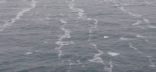
Figure 67 - Photo of new ice (courtesy of CIS)
4.16.4.2 Nilas
Nilas is ice that has developed to the stage where it forms a thin elastic crust over the sea surface. The layer may be up to 10 centimetres thick and is characterized by a dark, matt appearance.
It has unique deformation characteristics that make it easy to recognize. It bends easily on a vessels wake, often without breaking, and when two sheets of nilas converge they may overlap in relatively narrow fingers (figure 68). New ice and nilas are not a hazard to shipping.
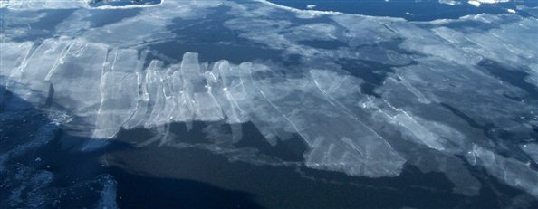
Figure 68 - Example of nilas (image courtesy of CIS)
4.16.4.3 Young ice
Young ice is ice that is between 10 and 30 centimetres thick. This category includes grey ice (10‑15 centimetres thick), and grey-white ice (15-30 centimetres thick). As these names suggest, young ice is most readily identified by its characteristic grey colour. Converging floes of grey ice will overlap, or raft, in wider fingers than nilas ice, and can extend to rafting of very large sheets. Extensive rubble fields are frequently observed, especially in grey-white ice.
Young ice achieves sufficient strength to present a potential hazard to vessels not strengthened for ice and will begin to slow down the speed of advance of low-powered vessels. Figures 69 and 70 are examples of young ice.
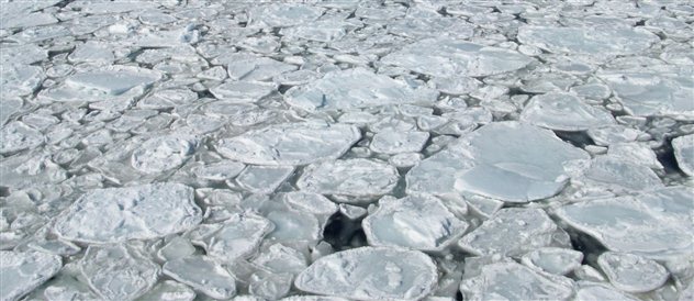
Figure 69 - Example of pancake ice (image courtesy of CIS)
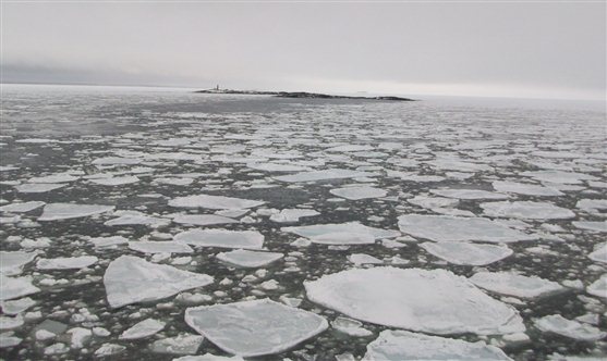
Figure 70 - Examples of grey and grey-white ice (image courtesy of CIS)
4.16.5 First-year ice
First-year ice is ice that is greater than 30 centimetres thick and less than 1 year old. It can be classed as thin, medium, or thick. However, it is often difficult to tell by looking at the ice how thick it is, because colour and surface characteristics are relatively constant. The thickness of block edges visible in ridges will indicate a minimum thickness but the level component may be thicker than this depending on how long ago the ridge was formed. The most accurate way to estimate ice thickness is by observing the edges of pieces as they turn against the ship's side. It is useful to know the dimensions of 1 or 2 deck-level objects (such as width of deck rail) which can be viewed from the bridge at the same time as the breaking ice pieces. Figure 71 shows an example of first-year ice.
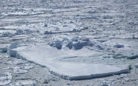
Figure 71 - Example of First-year ice
Old ice
Old ice is ice that is more than 1 year old and has survived at least one melt season. This category includes second-year and multi-year ice. During the melt period, puddles form on the first-year ice surface that because of their darker colour tend to absorb more solar radiation than the surrounding patches of white ice. Should the ice not melt completely before the onset of freeze-up, the undulating pattern will become a permanent feature of the ice surface. As the melt-freeze cycles are repeated, the ice grows progressively thicker and the difference between melt ponds and hummocks becomes more pronounced.
It is not always easy to distinguish second-year from first-year ice, as both snow cover and melt-water tend to hide the early stages of hummock growth. The component of the ice cover that is actually second-year ice is normally limited to the upper 50-100 centimetres, with the remainder being first-year ice growth. Thus second-year ice may be recognized when pieces turn on their side, by the presence of a distinct, cloudy boundary between the 2 layers which is several centimetres thick. Below the boundary, the first-year ice will usually be apparent from its slightly greener colour, and vertical structure of its columnar crystals. Figure 72 shows an example of second-year ice.
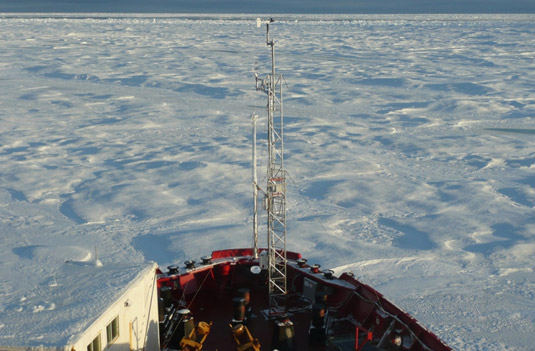
Figure 72 - Example of second-year ice (CCG)
Multi-year ice is easier to identify than second-year ice, primarily because the hummocks and melt-ponds become increasingly pronounced. In addition, there is normally a well-established drainage pattern connecting the melt ponds, and floes tend to have a higher freeboard than first-year ice. Where the ice is bare, the colour of multi-year ice may appear bluer than first-year ice.
Multi-year ice floes vary considerably in size, thickness, and roughness, depending on their growth history. Even when the surface is hidden by rubble or snow, it is frequently possible to identify these very strong floes by the first-year ice ridging which often forms around their perimeter. Many of these characteristics can be seen in the photograph of a typical multi-year floe, presented as figure 73. Multi-year ice is the strongest and hardest form of sea ice and represents a serious impediment - indeed a danger - to all vessels, as even the most powerful icebreakers will avoid contact with multi-year floes if at all possible.
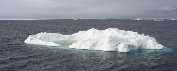
Figure 73 - Example of a small floe of multi-year ice (image courtesy of CIS)
4.16.5.1 Icebergs, bergy bits and growlers
Mariners should beware of leads in pack ice, which may suddenly end at an iceberg. Because icebergs project deep into the water column, they are affected more by ocean currents and less by winds than the surrounding sea ice. This may result in differential motion and the creation by the iceberg of an open water track through the pack ice.
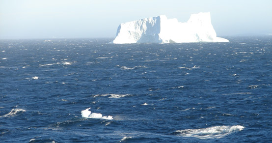
Figure 74 - Iceberg and growlers in the open sea (image courtesy of CIS)
Generally, the same comments apply to bergy bits and growlers as to icebergs. However, the smaller size of these hazards means they are often more difficult to detect than icebergs and, therefore, are very dangerous. Special care must be taken in watching out for bergy bits and growlers. They may be well hidden by white caps in the open sea, as shown in figure 74, or by rubbled ice, as shown in figure 75. Their shape may make even larger bergy bits difficult to detect using marine radar, when the freeboard is relatively small and if the sides are oriented to deflect radar energy away from the antennae. It is worthwhile to reduce speed while in bergy waters and to add an extra watch keeper to ensure that an adequate look out can be maintained. Bergy bits and growlers are the most dangerous hazards to vessels in ice-covered waters.
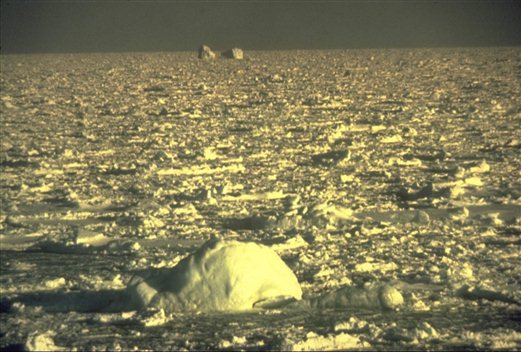
Figure 75 - Growler hidden in ice rubble (image courtesy of CIS)
Warning: The mariner must watch for bergy bits and growlers at all times when in bergy waters. Do not rely solely on marine radar to detect icebergs, bergy bits and growlers in fog and darkness.
4.16.6 Marine observations from vessels
Observations from vessels on weather, sea, and ice conditions are important sources of information for the Environmental science centres across Canada. Vessel observations allow the meteorologist:
- to know where the vessel is and to focus on that area
- to confirm a forecast with actual data during the forecast period
- to learn in real time what winds are produced by various pressure patterns in a given area
- to learn which forecasting techniques are appropriate for a given area, for example, to forecast sea conditions, vessel icing, and ice motion
Direct observations from vessels are incorporated on weather maps and analyses. There is a special need for observations from vessels transiting Hudson Strait and Hudson Bay, from fishing vessels in Davis Strait during November and December, and any vessels navigating in the Arctic.
In addition to using vessel observations in current forecasts, the information is stored by the Canadian Centre for Climate Services so that meteorologists can analyse it, for example to learn the means and extremes of wind for various marine areas. Engineers use the data to evaluate extreme events expected which could affect vessels and structures; they can develop and refine formulas to compute conditions such as sea state and vessel icing.
Observations can be passed to the appropriate SPC, listed in Section 1.7, or to the nearest MCTS centre which will forward the information to the SPC. No cost is involved. Weather, sea, and ice observations can be added to any position report given; for instance, all vessels operating in Arctic waters must provide a once daily position report. It is most useful to provide weather observations at the regular times of 0000, 0600, 1200, and 1800 UTC so that charts and forecasts can be updated.
- Date modified: